PROTECTIVE EQUIPMENT MSA (OBA) A-4
The Navy uses a wide variety of special fire fighter's
protective equipment. It includes the oxygen breathing apparatus, protective
masks, proximity suits, tending lines, and atmospheric testing equipment
plus gloves, helmet, anti-flash hood and voice amplifier. You will need to
know what equipment is available, how to operate it, and how to maintain it
in top operating condition.
OXYGEN BREATHING APPARATUS
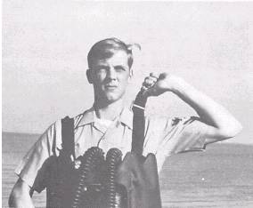
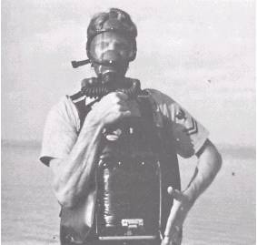
The type A-4 oxygen breathing apparatus (OBA) is used
throughout the Navy. The OBA is an entirely self-contained breathing
apparatus. It enables the wearer to breathe independently of the outside
atmosphere. It produces its own oxygen and allows the wearer to enter
compartments, voids or tanks that contain smoke, dust, or fire, or those
that have a low oxygen content.
Major OBA Components
You will be required to wear, operate, and maintain in
perfect operating condition the type A-4 OBA. To do so, you must know the
various components of the OBA and their purposes. Figure 6-1 shows the
components and identifies them. As you read about the various components,
refer to this figure as well as to those pertaining to the individual
components.
FACEPIECE.-
The facepiece (fig. 6-2) contains the
eyepiece, the speaking diaphragm, and the head straps. The eyepiece is a
one-piece clear lens. A spectacle kit is provided that may be installed in
the facepiece. Corrective lenses may be installed in the kit for individuals
who require glasses. However, once the lenses are installed, only the person
that the lenses are made for can 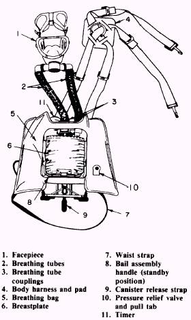
Figure 6-1.-Components of the OBA.
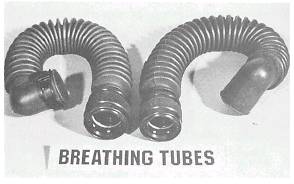
Figure 6-3.-Breathing tubes.
tubes to control the oxygen. The breathing bag
contains the oxygen that is generated by the canister for you to breathe.
One breathing tube transports the oxygen from the breathing bag to the
facepiece (fig. 6-3); the other transports the exhaled air back to the
canister. Both tubes are made of corrugated rubber. They control the flow of
air and help cool the air for your comfort when you wear the OBA. The tubes
are a quick-disconnect type. The tube couplings are color coded, and the
supply tube is of a different size than the exhaust tube. This prevents the
possibility of connecting the tubes to the wrong couplings.
TIMER.-
The timer (figs. 6-1 and 6-4) is located so
that you can check the amount of
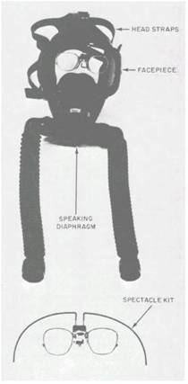
Figure 6-2.-Facepiece with spectacle kit installed.
use that spectacle kit. The speaking diaphragm allows
you to talk to others and to use communication devices such as sound-powered
telephones. The head straps hold the facepiece snug against your face. If
the straps are adjusted properly, no outside gases can get inside of the
facepiece.
BREATHING BAG AND
TUBES.-
The OBA has a breathing bag and two breathing
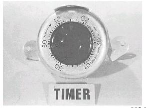
Figure 6-4.-Timer.
time remaining as you go about your duties. The
timer's bells are made to ring for 8-10 seconds continuously.
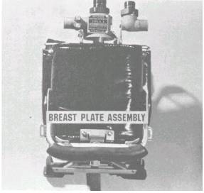
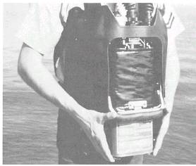
BREASTPLATEASSEMBLY.-
The breast-plate assembly (fig. 6-5) houses the plunger assembly, canister
guard and holder, and the handle. The plunger pierces the copper foil seal
of the canister when the canister is seated in place. The handle actuates
the seating mechanism that positions the canister in its housing. When
activated, the canister's chlorate candle provides you with oxygen to
breathe. The canister gets very hot, but the canister guard or holder
protects you from the heat produced by the canister.
COMBINATION VALVE ASSEMBLY.-
The combination valve assembly is shown in figure 6-6. It directs the flow
of air through the canister to the breathing bag.
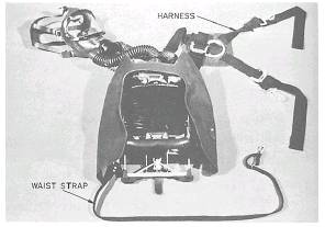
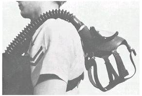
HARNESS AND WAIST STRAPS.-
The OBA has two types of straps: harness and waist (fig. 67). The harness
straps go over your shoulders and snap into D rings. They support the weight
of the OBA. The waist strap goes around your body and helps keep the OBA
from swinging away from you.
OBA
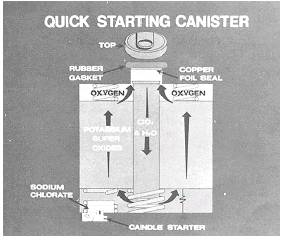
QUICK-STARTING CANISTER.- The quick-starting canister (fig. 6-8) is painted
Figure
6-5.-Breastplate assembly.
Figure
6-6.-Combination valve assembly.
green.
This is the canister that you will use for all evolutions other than
training. The training canister is discussed later. Figure 6-9 shows a
cutaway view of the canister. The rubber gasket provides an airtight seal
when the canister is in the operating position in the OBA. The copper foil
seal protects the chemicals from moisture until the canister is ready for
use. The chlorate candle, which is built into the canister, produces oxygen
for about 5 minutes. You will be able to breathe in the oxygen and exhale it
just as if you were not wearing an OBA. The moisture and carbon dioxide from
your exhaled breath activate the chemicals in the canister. The chemicals in
the canister cleanse your exhaled breath of the moisture and carbon dioxide
Figure
6-7.-Harness and waist strap.
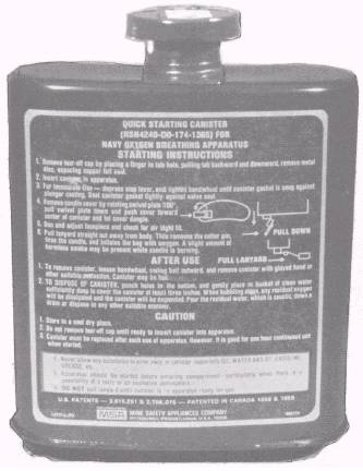
Figure
6-8.-Front view of quick-starting canister for use with Type A-4 oxygen
breathing apparatus.
Figure
6-9.-Cross-sectional view of quickstarting canister.
and
return the remainer of the air to you as you inhale.
The
amount of your exertion will deter-mine how long the canister produces
oxygen. The more active you are, the faster the chemicals will be expended.
The canister will last longer when you are doing mild work such as
investigating shipboard damage. When you are involved in hard work, such as
fighting a fire, the canister will last for about 30 minutes. Your normal
breathing habits will also effect the length of time the canister will last.
When you replace an expended canister with a new canister, do so only in
fresh air.
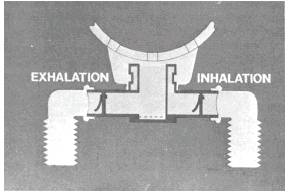
Airflow
System
At this
point, you should know and understand the use of each component of the
OBA.
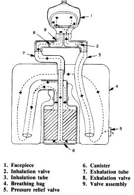
Figure 6-10 shows an OBA with a canister installed. The arrows indicate the
airflow through the OBA.
As you
exhale, moist breath passes through the exhalation tube (7), through the
valve housing to the bottom of the canister (6), and upward through the
chemical. The carbon dioxide is absorbed, and the moisture present reacts
with the chemical to give off oxygen. This oxygen passes into a breathing
bag (4) (part of the breastplate group) from which the inhalation tube (3)
allows the breathable mixture to be drawn into the facepiece (1) by your
normal intake of breath.
Check
valves (2 and 8) are used in the inhalation and exhalation passages. An
automatically operated pressure-relief valve (5) in the breathing bag
relieves excess pressure in the breathing bag. The speaking diaphragm, as
described earlier, is built into the facepiece.
Figure
6-10.-Airflow system.
OBA
Operating Procedures
Damage
Controlmen use the OBA on a regular basis for fire-fighting and training
purposes. It will protect you; however, improper use of the OBA could make
you a personnel casualty. The following topics discuss the type A-4 OBA
operating procedures. It is very important that you learn to use them
properly. You should practice the operating procedures under the supervision
of a leading petty officer who is qualified in the use of the OBA. Do not
use the green quick-starting canister for training; check with the DCA about
using a red training canister.
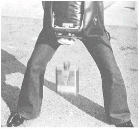
DONNING
THE OBA.- When donning the OBA, do so in the following order:
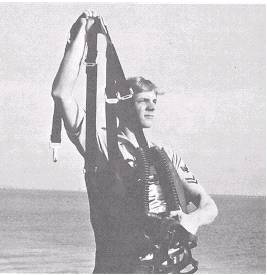
1. With
one hand, grasp the facepiece at the combination valve housing and the
apparatus at the operating handle. With the other hand, grasp the straps of
the body harness and the body pad D ring. Bring the pad and harness over
your head while positioning the OBA on your chest. See figure 6-11.
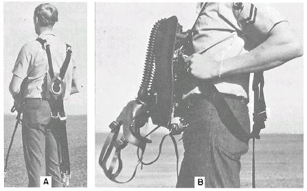
2. Find
the two straps hanging free in back (view A, fig. 6-12). Attach the end of
Figure
6-11.-Step 1 of donning the OBA.
Figure
6-12.-Step 2 of donning the OBA.
each
strap to the ring on each side of the breastplate (view B, fig. 6-12).
3.
Position the breastplate on your chest so that the breathing tube
connections are slightly below your shoulders. Your head movement should not
be restricted when you don the facepiece. While holding the apparatus in
this position, adjust the two underarm straps and then adjust the two
shoulder straps (fig. 13)
Figure
6-13.-Step 3 of donning the OBA.
until
the apparatus fits comfortably. The harness pad should be located in the
center of your back down from the neck for a comfortable fit.
4. Place
the facepiece over your head in the standby position (fig. 6-14) until you
are ready to activate the canister.
5. Snap
the waist strap to the bracket on the lower side corner of the breastplate
Figure
6-14.-Step 4 of donning the OBA. 6-7
Figure
6-15.-Step 5 of donning the OBA.
(fig.
6-15) and adjust to hold the apparatus snugly to your body. To secure the
excess loop of the waist strap, wrap it under the secured part of the strap.
Secure the ends of the lower body harness straps under the waist strap if
they extend down to your waist after being adjusted.
6.
Install the canister in the following manner:
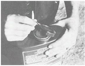
a.
Remove the tear-off cap of the canister by pulling the tab backward and
downward to expose the copper-foil seal (fig. 6-16). Discard the cap.
b.
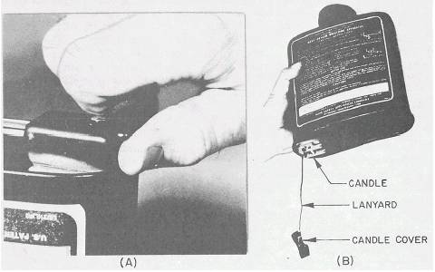
Remove the canister candle cover by rotating the swivel plate 1800. Push it
down toward the center of the canister, as shown in view A of figure 6-17.
Leave the cover dangling by the lanyard, as shown in view B of figure 617.
When you remove the candle cover, do NOT
pull the
lanyard so that the cotter pin is removed. The removal of the cotter pin
fires the candle, and the canister starts generating oxygen. If this happens
while the copper-foil seal is intact, internal pressure in the canister will
build up. This pressure will cause the copper foil seal or the canister seam
to rupture.
c. Hold
the canister with the neck up and the concave, or ribbed side, toward your
body. Insert the canister upward into the guard and breastplate assembly
(fig. 6-18) until the canister is firmly in place. The canister is now
locked in a standby position with the copper-foil seal still intact. If the
copper-foil seal is pierced when the canister is placed in the standby
position, the standby stop will need to be adjusted. An OBA that pierces the
copper-foil seal in the standby position is NOT to be used until the
adjustments are made.
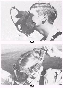
7. Don
and adjust the facepiece as follows:
a. Place
the head harness straps over the front of the facepiece.
b.
Insert your chin into the chin stop of the facepiece (view A of fig. 6-19).
c. Pull
the head straps from the front of the facepiece over your head (view B of
fig. 619). Be sure your hair is not under the facepiece shield.
d. Make
sure the straps lie flat against your head.
e.
Tighten the lower straps (neck straps) first.
f.
Tighten the side straps.
g. Place
both hands on the head harness pad (on the back of your head) and push it
down toward your neck.
h.
Repeat steps e and f.
Figure
6-16.-Step 6 removing tear-off cap.
Figure
6-17.-Removing the candle cover, views A and B.
i.
Tighten the forehead or front strap, if needed.
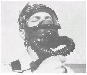
8. Test
the facepiece for a good seal by squeezing the corrugated breathing tubes
tightly to prevent the passage of air (fig.
Figure
6-18.-Inserting the canister.
Figure
6-19.-Donning the facepiece, views A and B.
6-20).
Inhale gently so the facepiece collapses slightly, and hold your breath for
10 seconds. The facepiece will remain collapsed while your breath is held if
the assembly is gas tight. If you detect any leakage around the face seal,
readjust your head harness straps. If you detect other than face-seal
leakage, investigate the condition and correct it. You MUST test the
facepiece for a seal before each use.
9. Make
final adjustments on all four body harness straps. You should be able to
look up or down without having the facepiece shift or catch on the timer or
the main valve housing.
10. If
you are going into a standby or ready condition, loosen only the lower
facepiece straps and then remove the facepiece. Place the facepiece over
your head and out of the way until ready to start the canister and put the
OBA into operation. In an emergency, eliminate this step.
STARTING
THE CANISTER.- When you are ready to enter the contaminated area, start the
canister in the following manner:
1. If
your facepiece is in the standby position, put it on before starting the
canister. Retighten the lower straps and retest your facepiece for a proper
seal.
2.
Unlock the bail assembly handle of the OBA by using both hands to depress
the tabs from the bottom lock. Swing the handle upward until it snaps. Test
the handle to see if it is locked by
Figure
6-20.-Airtightness of the facepiece.
lightly
pushing the handle forward without depressing the tabs.
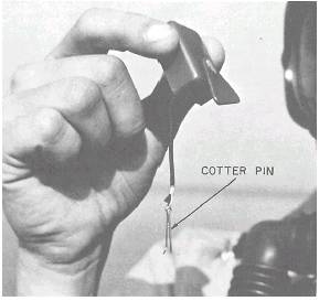
3. Pull
the lanyard on the canister straight out and away from your body. This
removes the cotter pin (fig. 6-2 1), fires the candle, and inflates the
breathing bag with oxygen. After you pull the lanyard, always check to
ensure that the cotter pin is still attached to the lanyard. A slight amount
of harmless smoke maybe present in the facepiece while the candle is
burning.
4. Now,
test the tube connectors, canister, and breathing bags for tightness. While
the candle is filling the breathing bag, depress the breathing bag at the
pull tab with your left hand. Regrasp and seal off both breathing tubes with
your right hand, while pressing against the right side of the breathing bag
with your right elbow (fig. 6-22). The bag must be compressed at the pull
tab so that the relief valve does not vent during this test. The bag must
remain inflated; otherwise, there may be a leak in the OBA, which you must
correct before you use the OBA.
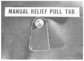
5.
Breathe normally. The chemical reaction of the canister will generate more
oxygen than you require. If too much oxygen is produced, the extra oxygen
will be vented automatically by the relief valve in the bag when the bag
reaches full capacity. A manual relief pull tab on the valve (fig. 6-23) is
provided in case the valve sticks in the closed position during a long
period of storage. DO NOT pull the breathing bag tab
Figure
6-21 .-Checking for the cotter pin.
Figure
6-22.-Testing the OBA.
during
normal use. If you do, you will vent your breathing oxygen from the
breathing bag to the atmosphere.
In the
event of a malfunction of the candle, you can activate the canister
manually. The manual starting of the canister is not recommended. The
procedures listed here are to be used only when the chlorate candle has
misfired and sufficient time is available to start the canister manually, or
if there is a shortage of available canisters. Under no circumstances should
you save
Figure
6-23.-Manual relief valve tab.
the
chlorate candle to use for an emergency exit of the space. Such practice is
dangerous, and the candles have been known to misfire.
You must
be in a clean atmosphere when manually starting the canister. Use the
following procedures:
1. Work
one finger under the edge of your facepiece, stretching the mask slightly to
break the seal.
2.
Inhale while grasping and squeezing both breathing tubes with your other
hand. This will allow you to draw external air from outside the facepiece.
3.Release the breathing tubes, remove your finger to reseal the mask, and
exhale into the facepiece.
4.Continue this cycle until your breathing bag is fully inflated. Exhaust
the air in the breathing bag by exerting pressure on the right-hand side
until the bag on the right is deflated. In this process, your moist breath
passes through the canister to start the chemical reaction. One filling of
the bag is not usually sufficient to fully activate the canister
5.
Repeat steps 1 through 4 to reinflate and deflate the breathing bag at least
five times. Now, without gloves, cautiously feel the bottom of the canister.
If the entire bottom of the canister is warm, oxygen is being generated. The
apparatus is then ready for setting the timer and for the operational check.
If the canister is not warm, repeat steps 1 through 4. In cooler
temperatures, several cycles of inflation and deflation of the bag may be
required to start oxygen production.
SETTING
THE TIMER.- To set the timer, grasp the knob on the timer. Turn the knob
clockwise to 60 minutes, and then turn it counterclockwise to 30 minutes. By
setting the timer to 60 first, you fully wind the alarm bell spring. When 30
minutes have expired, the warning bell will sound continuously for 10 or
more seconds. When you have set the timer, you are ready to enter a
hazardous atmosphere.
REMOVING
AN UNUSED CANISTER.- If the canister's copper-foil seal has not been
punctured, remove the canister by placing one hand on the bottom of the
canister and pulling the canister releasing strap. You do not need to wear
gloves in this situation. The handle must also be in the load and standby
positions.
Once the
canister is removed, protect the copper-foil seal by installing one of the
spare aluminum caps that are provided for this purpose.
REMOVING
A USED CANISTER.- When you remove a hot canister, you need to protect your
hands with approved protective gloves.
Once the
canister has been used, remove the facepiece and put it over your head in
the standby position. Then, unlock the handle from the operation position
and swing it down to the load and standby positions.
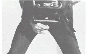
Next,
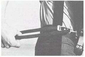
unfasten the waist strap, spread your feet apart and lean the upper part of
your body slightly forward. To release the used canister, pull the canister
release strap (fig. 6-24). The canister will drop out of the apparatus (fig,
6-25). Drop the canister ONLY on a clean, dry deck.
You need
to be careful when you remove used canisters from the OBA. They are hot, and
the chemicals inside of the canister can cause serious chemical burns if
they get on your skin. The chemicals are similar to caustic soda, also known
as lye. Normally, you will not have chemicals spilling out of the canister,
but there is always the possibility. Finally, the chemicals will cause a
violent explosion if they come into contact with a petroleum-base substance.
DISPOSAL
OF USED CANISTERS.- You must dispose of an OBA quick-starting canister as
soon as possible after it has been used or when the copper-foil seal has
been punctured.
If your
ship is more than 25 nautical miles from shore, you may throw the canister
overboard. To dispose of the canister in this manner, first obtain
permission from the officer of the deck. Once permission has been granted,
ensure that the canister cap is removed and the copperfoil seal is fully
punctured. This will allow water to enter the canister. DO NOT puncture
holes
Figure
6-24.-Releasing the canister.
Figure
6-25.-Dropping the canister.
in the
bottom or sides of the canister. Make sure there is no oil in the water.
Then throw the canister overboard. If oil gets inside of the canister, a
violent explosion will occur.
If you
are within 25 nautical miles of shore, do not throw the canister overboard.
Instead, let it cool down for at least 30 minutes. (If a canister was not
used, but the copper-foil seal has been punctured, place the canister in a
clean bucket. Light off the canister and let it set for 15 minutes to cool.)
When the canister is cool enough to handle, place a new metal cap, NSN
4240-00-089-7963, on the neck to cover the punctured copper-foil seal. Then
double wrap the canister in a poly bag, NSN 8105-00-2998532, or its
equivalent. The wrapped canister should then be stored in a dry, oil-free
area until it can be disposed of at sea or turned over to a shore facility
for disposal.
When the
ship is in port, contact the department ashore that is responsible for
hazardous waste. Make arrangements with that department to turn all
canisters over to them for disposal.
REMOVING
THE OBA.- Remove the OBA in the following manner:
1.
Remove the facepiece by releasing the head straps at the buckles with your
fingertips before pulling the headpiece off. If the canister is still in the
OBA, place the facepiece over your head
in the
standby position and remove the canister. NEVER remove the OBA with a
canister in place.
2. If
the facepiece is in standby position, you should remove it and let it hang
in front of the OBA.
3.
Loosen the waist strap, then unhook it.
4.
Loosen the shoulder straps and unhook the harness at the upper corners of
the breastplate assembly. Grasp the facepiece and operating handle with one
hand and the shoulder harness (preferably at the D-ring connector) with your
other hand. Lift the OBA over your head.
5. If
the OBA is wet or moist, wipe it down.
6.
Always clean the outside body of the OBA after each use with a mild solution
of soap and warm water.
7.
Disinfect the inside of the facepiece. Mix the disinfectant (NSN
95-6840-00-526-1129) as stated on the container label. Use a sponge that is
moist, but not dripping, with the disinfectant solution.
OBA
Equipment Stowage
Before
stowing the OBA, the facepiece should be protected to prevent scratches and
abrasions. All OBA equipment and canisters must be stored in a cool, dry
place. The life of an OBA will be
Figure
6-26.-OBA storage locker.
lengthened if it is stored under these conditions. The term cool denotes
temperatures ranging from above freezing to 110°F (43°C) when storage is out
of direct sunlight. The term dry usually denotes a storage area where
condensation does not come in contact with the equipment.
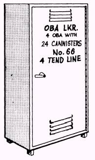
The only
places the OBA should be stowed onboard ship are in repair lockers or in OBA
lockers (fig. 6-26). These lockers have provisions for stowing the OBA in a
flat position. You should ensure that the facepiece is properly protected to
prevent scratching or scarring of the lens. The canisters should be stowed
with the concave side down. Additional information on cleaning, inspecting,
and testing of the type A-4 OBA can be found in the Naval Ships'
Technical Manual, chapter 079, volume 2.
TENDING
LINES
Tending
lines are used as a precautionary measure to help rescue an investigator or
fire fighter who is wearing an oxygen breathing apparatus, air-line mask, or
similar equipment.
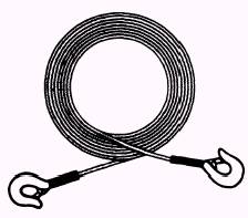
A
50-foot nylon covered, steel wire tending line (fig. 6-27) is used aboard
ship with the oxygen breathing apparatus or the air-line mask. The tending
line has a stout hook on each end that is closed with a snap catch. The line
is pliable and can slide freely around obstructions.
If
necessary, the rescue should be accomplished by having another person
equipped with a breathing apparatus follow the tending line to the person to
be rescued. Do not attempt to drag the person out by the tending line. The
line may become fouled on some obstruction or part the wearer's harness.
This will mean a loss of time,
Figure
6-27.-Tending line.
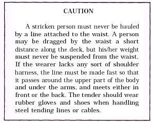
CAUTION
A stricken person must never be hauled by a line attached to the waist. A
person may be dragged by the waist a short distance along the deck, but
his/her weight must never be suspended from the waist. If the wearer lacks
any sort of shoulder harness, the line must be made fast so that it passes
around the upper part of the body and under the arms, and meets either in
front or the back. The tender should wear rubber gloves and shoes when
handling steel tending lines or cables.
and it
will still be necessary to send another person in. If the rescue is to be
effected promptly, someone must be equipped with an OBA that is ready for
immediate use and must be standing by ready for immediate entry. Tending
lines may also be used by fire fighters to find their way back to fresh air
to change canisters when the visibility is poor because of heavy smoke.
When the
OBA is used to inspect damage or to fight fires, a team of one wearer and
one person to handle the tending line should work together. If two or more
OBAs are used in the same compartment, the tending lines are not used.
However, the personnel wearing the OBAs should keep in constant sight or
touch with each other.
The OBA
wearer and the line tender should both know and use the following system of
line signals
|
Code
|
Pull
|
Meaning |
|
O
|
1
|
OK
|
|
A
|
2
|
Advance |
|
T
|
3
|
Take
up |
|
H |
4 |
Help |
OBA
TRAINING CANISTER KIT
The OBA
training canister kit-FSN 2H-424000-238-9959--(fig. 6-28) is designed to
provide realistic training in the classroom for 40 trainees. These trainees
don the OBA and properly activate the quick-start OBA (training) canister.
The training canister is red in color and is functionally identical to the
regular green quick-start canister.
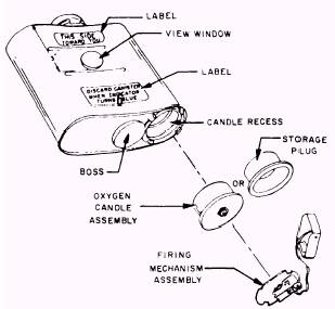
Figure
6-28.-Training canister assembly-exploded view.
However,
there is one important distinction: The training canister contains a
chemical filler (baralyme), which only absorbs the carbon dioxide (CO2) from
exhaled breath. It does not produce oxygen. There is enough baralyme to
absorb the CO2 that will be exhaled by the 40 trainees who use the canister
for 5 minutes each AT REST.
NOTE:
The canister should be discarded after it is used by 40 trainees, or when
the chemical in the view window of the canister body changes color from pink
to solid blue, whichever occurs first.
The
oxygen candle assembly produces about 10 liters of oxygen. In the training
canister, this is enough to provide 5 minutes of oxygen for one person AT
REST. The danger of a training canister being used during an actual casualty
is obvious. To prevent inadvertent use and possible serious injury or a
fatality, the training canisters should NEVER be stowed in OBA lockers or in
the vicinity of damage control equipment.
For the
initial charging of a training canister, use the following procedures:
1.
Remove the cover from the firing mechanism. Remove the firing mechanism and
storage plug. Save the plug to reuse when storing a partially used canister
to prevent moisture from entering the canister body.
2.
Insert a candle assembly into the candle recess of the canister. Make sure
the gasket is flat against the bottom of the canister.
3. Place
the firing mechanism over the candle assembly with the primer housing
projecting through the center hole and with the notches lined up with the
tangs. The notches and tangs are positioned so that the unit can only be
assembled in the correct position.
4.
Rotate the firing mechanism clockwise to lock the candle in place. Tighten
the firing mechanism until the frame contacts the tangs. Do not overtighten.
5. Fold
the lanyard into the candle cover and secure the assembly on the firing
mechanism frame. The training canister is now ready for use with the OBA.
To
recharge a canister that has just been used, use the following procedures:
1.
Position and secure a new metal tear-off cap on the canister neck so that
the tab points toward the instruction label on the convex side of the
canister.
2.
Remove the firing mechanism from the bottom of the canister by turning it
counterclockwise until the tangs line up with the notches.
3.
Remove the used candle and place it in a regular trash can after it has
cooled.
4. Hold
the firing mechanism (fig. 6-29) with the slotted end of the frame pointing
toward you. Raise the firing hammer to the cocked position.
5. While
holding the firing hammer in the
cocked
position, insert the cotter pin through the holes in the frame from the same
side as the rivet head. Secure the cotter pin by bending the long leg
slightly.
The
remainder of the recharging procedure is the same as steps 2, 3, 4, and 5 of
the initial charging procedure.
To start
a training canister after it has been charged, use the following procedures:
1.
Remove the tear-off cap from the top of the CHARGED canister by pulling it
straight backward and downward; remove the disk to expose the gasket.
2.
Remove the candle cover by rotating the swivel plate 180°; push the swivel
plate and cover down toward the center of the canister. Let the cover dangle
on the lanyard. DO NOT PULL THE LANYARD.

Figure
6-29.-Detailed assembly of firing mechanism.
3.
Insert the training canister into the OBA to the standby position.
4. Move
the training canister into the operating position by lifting the handle
upward, ensuring that the canister is snug in the canister guard.
5. Don
and adjust the facepiece, and check it for an airtight fit.
6. Pull
the lanyard straight out away from your body. This removes the cotter pin
and fires the candle, which inflates the bag with oxygen within 15 seconds.
7. Set
the timer on the OBA by turning it clockwise to 60; then, return it to 5.
To
remove the canister, you should follow the same procedures used for removing
an unused canister (discussed earlier in this chapter). However, you must
wear protective gloves because the canister will be hot. If the canister is
to be reused by another person, charge it as previously discussed.
Training
Kit Stowage
Training
canister kits are to be stowed in a special locker provided or in a locked
compartment. This kit is to be kept locked at all times, except when it is
in actual use. The keys should be controlled by the damage control officer
to
ensure that the training canisters are used only for training.
After
training sessions or for breaks in training of 1 hour or more, a partially
used canister should be sealed. To seal the canister, place a metal tear-off
cap on the canister neck, remove the oxygen candle, and lock the plastic
storage plug in the candle recess in the canister bottom by the firing
mechanism. The canister should be returned to the special locker or
compartment and locked. Where lockers are not provided, stow the canister in
a cool, dry storeroom.
Training
Kit Disposal
After
the chlorate oxygen candles have been burned, they contain sodium chloride
(table salt) and partially oxidized iron. They may be discarded in a regular
trash container after they have cooled.
Expended
training canisters do not have the hazards of the regular quick-start
canister. However, for the training benefit, they should be disposed of in
the same manner as the regular quick-start canister.
|