|
|
|||||
|
|
|||||
|
|
|
||||
| Onderhoud aan de APEKS eerste trap |
Overhaul an APEKS First Stage Regulator |
||||
|
Model T20/US4 Unsealed Non-Turret Din aansluiting |
Model T20/US4 Unsealed Non-Turret Din aansluiting |
||||
|
|
|||||
| WAARSCHUWING: Dit onderhoudsschema is opgesteld voor persoonlijke studie. Het is onveilig om een eerste trap te servicen zonder APEKS fabriekstraining en certificering. De schrijver en publicist van dit schrijven wijst elke verantwoordelijkheid af met betrekking tot de onderhoud van drukregelaars, zelfs voor getrainden. Zie ook de disclaimer. Veiligheid betekend het nemen van voorzorgsmaatregelen om ongelukken van welke aard dan ook te voorkomen. Dit artikel vervangt geenzins training als gegeven voor Apeks apparatuur. Ik raad personen zonder technische kennis en opleiding af de onderbeschreven handelingen uit te voeren. Dit artikel is niet meer dan een beschrijving hoe de apeks drukregelaar wordt onderhouden, en het is af te raden dit zelf uit te voeren. | A WORD OF CAUTION: This plan is for academic study only and is not complete. It is unsafe to service any regulator without APEKS factory training and certification. The reader assumes all responsibility for safety and safe use of what they choose to service, even after training. Safety means you make provision to protect yourself from injury of any kind. This article is not a replacement for APEKS factory training and their course of instruction on SCUBA regulators. I am not advocating the service of any SCUBA regulator by someone who is not trained and certified in such practice. This article is nothing more than a story about APEKS regulator overhauls and insists that you, the reader, NOT undertake such a task. | ||||
| Introductie: Voor ik begin aan de revisie van mijn eerste trap , heb ik een aan speciaal gereedschappen nodig. Enkele eenvoudige gereedschappen heb ik al zoals metrische steeksleutels, een bankschroef met zachte bekken, en een tandarts haak. De speciaal gereedschappen die ik nodig heb zijn een manometer voor het meten van de middendruk (IP), een 40-42 Gedore haaksleutel met ronde grip pen, en een ultrasoon reinigings bad. De meeste onderhouds bedrijven voor ademautomaten service bezitten een magnehelic drukmeter. Deze meter is slechts nodig voor onderhoud aan tweede trappen en is hier overbodig. De IP- drukmeter is voor het meten van de middendruk op de lagedruk (LP) uitgangen. Voor het inregelen van de middendruk wordt voor de inspiration de waarden uit de fabrieksmanual gebruikt. |
Introduction: Before I began to overhaul my regulator, I needed some special tools and a rebuild kit. Some simple tools I already had, like metric allen wrench's, vice with soft jaws, and dentist's pick. The special tool's required were an IP (Intermediate Pressure) gauge (below right), 40-42 mm spanner wrench (below left), and ultrasonic cleaning machine. Most regulator mechanic's have a flowbench which includes IP and magnehelic gauges. The magnehelic gauge is only required for the second stage rebuild so will not be discussed here. The IP gauge was used to determine the output pressure of any low-pressure (LP) port. For this job, it was necessary to set the IP pressure to about 130 PSI, and this is discussed further later in the story. For the Inspiration rebreather the IP is set conform the fabric manual's values. |
||||
 |
|
||||
| Iemand
wees mij op een goede bron voor gereedschap dat wordt gebruikt voor
automaten reparatie. Dit is www.scubatools.com
Hoewel dit artikel de T20 eerste trap behandeld, wordt door hun ook
gereedschap voor andere modellen aangeboden. Zo is onder meer te vinden:
PN 20-235-200 Haaksleutel $12.50 PN 20-236-200, Cover Tool $10 |
Someone brought to my attention that a good source of tools for
regulator repair is www.scubatools.com
- Although this article covers the T20 model of 1st stage regulator, they
do have tools especially designed for other APEKS models. The tools
I am referring to are: This is a custom spanner made from aluminum which will remove/install the cover on the TX100 regulator. In addition, they have all sorts of other neat tools designed for regulator repair that you will not find anywhere else! Check this stuff out!! www.scubatools.com/Universal.html www.scubatools.com/PBUniversal.html www.scubatools.com/Bench.html
|
||||
 |
|||||
| Iemand heeft me wel eens een methode uitgelegd die de service mogelijk maakte zonder het gebruik van een IP manometer. Hoewel dit mogelijk is prefereer is het gebruik van deze manometer om een nauwkeurig resultaat te garanderen. Deze methode wordt uitgelegd in Vance Harlow's SCUBA Regulator Maintenance and Repair, beschikbaar bij Airspeed Press, een goede | I have been told that its not necessary to use an IP gauge and there are methods to get around not using one, but thought it best to use one to ensure the accuracy and safety of my job. These issues are documented in Vance Harlow's SCUBA Regulator Maintenance and Repair, available from Airspeed Press, a good how-to text. The only downside to the manual is its generality. However, it does contain a schematic for the APEKS, an invaluable piece of reference material. Also, some suggested that an ultrasonic cleaner was not needed and proposed using a simple tooth-bush and vinegar for cleaning. I have found that a tooth-bush does not do as thorough a job since its impossible to get the brush inside every nook and cranny of the regulator. I ended up using the ultrasonic cleaner and was very pleased with the results. | ||||
|
|
|||||
| Een revisie kit zou de O-ringen en een hogedruk zitting moeten bevatten. Het blijkt echter niet eenvoudig deze sets te betrekken. Laat je niet misleiden door winkels die het voor je kunnen bestellen onder het mom van 'ik mats je hiermee', en vervolgens absurde prijzen rekenen. In Amerika worden deze revisie sets voor $20-$40 verkocht. Reken hier de verzendkosten bij en je hebt een aardige indicatie.De "diveinn" website www.scubastore.com verkoopt wat zij noemen een "APEKS TX Range 2 Stage Kit" voor ongeveer $14 ($26 met verzending in de USA) en dit is vermoedelijk de juiste set. Controleer dit echter zorgvuldig voor de set aan te schaffen. Je kan deze setjes vinden onder "automaten onderdelen" op hun website. Er staat bij vermeld dat je een APEKS training moet hebben gevolgd om de onderdelen te kunnen kopen.(Zie volgende paragraaf). De aankoop van deze setjes is behoorlijk lastig. De oorzaak is te vinden in een stukje protectie van het merk. Dit soort revisies dient uitgevoerd te worden door professionals en niet door iedere willekeurige duiker. Helaas hebben echter dezelfde professionals door slecht uitgevoerd werk mij gedwongen deze revisie zelf uit te voeren. (voor de Nederlandse lezers, zie overigens test onderhoud ademautomaten in het blad Onderwatersport 2001!) | A rebuild kit contains
the O-rings and high pressure (HP) seat you need to complete this job.
I was not discouraged about purchasing the rebuild kit. They can be
obtained, but realized persistence was necessary in this regard. I
knew of several shops that would sell them, but was careful. Some
shops thought they are doing me a favor and attempted to charge an
outrageous price. Kits should sell for somewhere between $20-$40
depending on the kit supplier. The "diveinn" website www.scubastore.com
does sell what they call an "APEKS TX Range 2 Stage Kit" for
about $14 ($26 with shipping), and this appears to be a rebuild kit, but I
am just guessing here. You will find it under the regulator spare parts
section of their website and it states you need APEKS training to purchase
it (see the next paragraph). Purchasing these kits has not been made easy,
and it all goes back to the attitude by professionals that the average
person on the street can't do this job or even be allowed too. In
fact, it has been poor workmanship by shops which forced me to undertake
this task myself. If you already have a good and reliable mechanic
that you can trust, then I would recommend you stick with them. They are
worth their weight in gold! For many years I had a shop that did a
great job for me, but their mechanic eventually left and then I was back
to square one. It was then that I worked out the details for this
overhaul myself and decided to write a story about it. I am not
advocating you undertake this task yourself, but rather locate a good
professional mechanic and let them do it for you. |
||||
 |
|||||
| Defenitie:
LP
(lagedruk) en HP (hogedruk) zijde van de eerst trap |
Definition:
|
||||
| Note: Dit artikel behandeld de meest eenvoudige versie uit de Apeks reeks ademautomaten. Heb je, als voorbeeld, de koud waterversie van de beschreven regelaar, of je hebt een extra geisoleerde versie, zullen de verschillen slechts klein zijn. Meer informatie over de verschillen van eerste trappen zijn gedocumenteerd in Vance Harlow's SCUBA Regulator Maintenance and Repair Manual als eerder hierboven genoemd. |
Note: This article documents the most simplest version of the APEKS family of regulators. If you have for example, the cold water version of the described regulator, or have the turreted version, the differences are minor. More information about the differences are documented in Vance Harlow's SCUBA Regulator Maintenance and Repair Manual discussed (above). |
||||
 |
|||||
| Stap 1: Verwijder alle schroeven uit de slangpoorten | Step One: First, I removed all the port plugs | ||||
 |
|||||
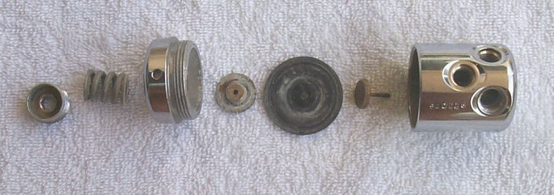
| Stap twee: Demonteer de Lagedruk
zijde. De haaksleutel is gebruikt om de membaandeksel los te draaien Onderdelen: (links naar rechts); stelschroef veerspanning, veer, membraandeksel, veerzitting, membraan, klepvork, behuizing |
Step Two: Next, I disassembled the LP side.
A spanner wrench was used to remove the diaphram cap. Parts (left to right): spring adjuster, spring, diaphragm cap, spring carrier, diaphragm, valve lifter, regulator housing |
||||
|
|
|||||
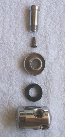
| Stap drie: Verwijder de Din connector | Step Three: Next, I removed the DIN connector. | ||||
| Onderdelen:(van boven naar beneden):Din steel, filter met O-ring, Dinschroefwartel, Vulstuk, behuizing | Parts (top to bottom, right photo): DIN stem, filter with O-ring, threaded DIN connector, distance piece, regulator housing | ||||
 |
|||||
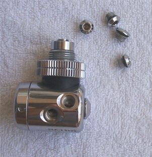
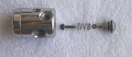
| Stap vier: Hierna demonteren we
de hogedruk zijde. Onderdelen (links naar rechts): Behuizing, Hogedruk klepzitting, veer, O-ring, plug met twee O-ringen |
Step Four:
Then I disassembled the HP side. Parts (left to right): regulator housing, HP valve seat, spring, O-ring, balance plug with two O-rings |
||||
 |
|||||
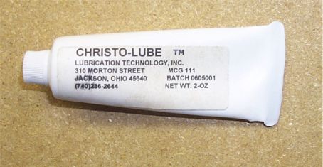
| Stap vijf: Tot slot, alle losse metalen onderdelen heb ik gereinigd in het Ultrasoonbad. Hierna alle spares uit het revisie setje gebruikt. Zonder hier nu zeer uitvoerig op in te gaan hier nog een aantal tips waarop moet worden geled bij de uitvoering van stap vijf: 1. Onthoud; demontage en montage begint aan de Lagedruk zijde! "De
meeste fanrikanten van Automaten gebruiken tegenwoordig Christo-Lube (note;
=zuurstof compatibel vet) voor elke automaat, zuurstofclean of niet. Dit
vanwege de uitmuntende smeereigenschappen. Zeagle, Apeks, Atomic, en
Oceanic zijn slechts enkele die ik uit het hoofd weet die uitsluitend dit
vet gebruiken. Hun officiele standpunt is dat Christo-Lube wordt gebruikt
in de gehele automaat, zuurstof clean of niet. Speciaal Apeks, zeker omdat
we het daar hier over hebben, verkoopt een zuurstof compatible
revisiesetje waarin alle O-ringen zijn gemaakt van Viton, voor zowel de
lagedrukzijde als de hogedrukzijde. Mede hierdoor is het argument
onderbouwd zuurstofcompatibel vet te gebruiken aan LP en HP zijde. (Voor
Inspiration gebruikers een Must). Feitelijk is er geen risico bij
het gebruik van zuurstof met een druk (<~300 psi), hier zou siliconen
vet dus toegepast mogen worden, echter de fabrikanten claimen een betere
prestatie door betere smering met Christo-Lube. Gebruik dus beter maar
geen Siliconen. Overigens acht ik het onwaarschijnlijk dat er 1 fabrikant
is die het gebruik van siliconenvet propageert voor een automaat in
zuurstofservice! 4. Als je vet toepast, gebruik het dan zeer zuinig. Zorg dat je de boel niet te vet maakt! 5. Aan de lagedrukzijde van de automaat smeerde ik alle delen licht in waar sprake was van metaal op metaal contact. Als voorbeeld: Ik smeerde de delen van de veer die de behuizing raken licht in met vet. Eveneens smeerde ik de draad in van de stelschroef voor de veerspanning. |
Step Five: Finally, I cleaned the metal pieces and replaced the parts from the rebuild kit. After I had gotten this far, I figured the rest was easy. As suggested above, I began by simply cleaning the metal pieces and replaced the worn out parts from the rebuild kit. In the interest of avoiding a long winded explanation, I will just state a number of especially important items that went into my notebook for future reference: 1. Remember, disassembly and re-assembly begins with the LP side 2. The regulator housing and various metal parts are manufactured to close tolerances, especially where the HP seat mates to the regulator housing. Be extremely careful not to go poking around with a dentists pick and destroy or scratch the metal inside the housing. A good way to remove the diaphram for example, would be to send a blast of air through one of the low pressure ports after removing the diaphram cap rather than using a dentists pick. 3. Be careful how you go about lubricating the O-rings and springs. For example, some persons have told me that on the HP side of the regulator, you should only use oxygen compatible (Christo-Lube or equivalent) lubricants. On the LP side, this is not an issue since its high-pressure and oxygen that causes problems, not low-pressure (<300 PSI). However, when I discussed this issue with several other knowledgeable persons, a factory trained person had this to say: "Most regulator manufacturers these days are using Christo-Lube for every regulator, O2 clean or not, because of it's superior lubricating qualities. Zeagle, Apeks, Atomic, and Oceanic are a few off the top of my head which are using strictly Christo-Lube so their official word is going to be use it in the whole regulator whether it's O2 clean or not. Apeks in particular, since that's what we're talking about, sells an O2 compatible conversion kit in which ALL O-rings are viton, both for HP side and LP side so it would stand to reason that they would recommend O2 compatible lube on both sides as well even if they weren't using it already. Fact is, as you know, you don't have the "O2 risk" at low pressure (<~300 psi) so silicone should be ok, but some of these manufacturers claim to have a measured increase in performance with Christo-Lube, so I use it everywhere. Due to liability fears, I don't think ANY manufacturer is going to say you can use silicone grease on a regulator being cleaned for O2 service." www.lubricationtechnology.com or even better www.scubatools.com/Universal.html 4. When you do apply any lubricant, use it sparingly. Do not gum up the works by over-lubricating anything. 5. On the LP side of the regulator, I used my choice of lubricant where there was metal to metal. For example, I put a light coating on both sides of the spring where it mates to the spring adjuster and spring carrier. I also put some on the threads of the spring adjuster. |
||||
 |
|||||
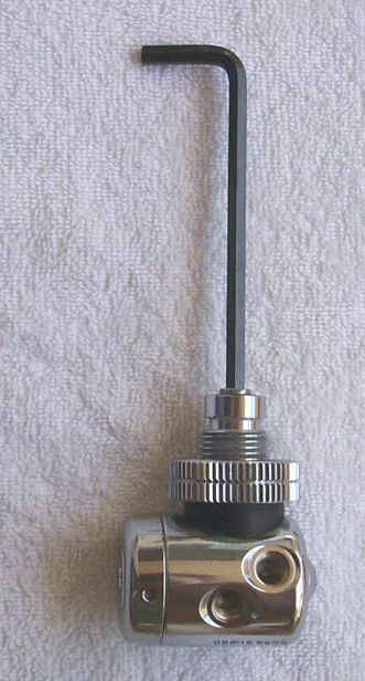
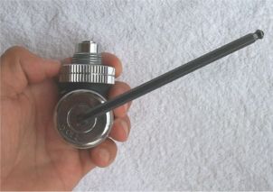
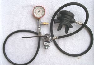
| Stap zes: Instellen van de middendruk. Ok na het reinigen en het weer in elkaar zetten van de eerste trap, voeren we de laatste betrekkelijk eenvoudige stap uit. Hiervoor hebben we een speciaal gereedschap nodig, de middendruk manometer. Op dit moment van de revisie bereiken we de stap om de middendruk in te stellen voor de uitgaande druk op de LP poorten. De LP poorten dienen ingesteld te worden op 130 PSI. (voor de inspiration rebreather gebruiker geldt een andere druk, welke is vastgelegd in de gebruikersmanual zoals verstrekt door de fabrikant!) De foto hierboven (links) toont de manier waarop de IP wordt ingesteld met behulp van een inbussleutel. De foto hierboven rechts toont op welke wijze de IP kan worden afgelezen en hoe de de manometer wordt geplaatst. (voor de Inspiration gebruiker kan de manometer op de Diluent slang of respectievelijk de Zuurstofslang worden geplaatst). In de foto rechts ziet U een tweede trap gemonteerd. De fungeert hier als overdruk ventiel. Bij de Inspiration wordt deze taak waargenomen door het overdruk ventiel op de eerste trap.De overdruk beveiliging voorkomt tevens het risico de manometer op te blazen. Tot slot; Ik heb ook nog een artikel gelezen over een bijzondere drukvariatie op de LP zijde. Dit artikel is te vinden in SCUBA Regulator Maintenance and Repair Manual. Drukvariatie op de LP zijde manifesteert zich als volgt: U sluit de eerste trap aan op een cilinder. De middendruk (middendruk) wordt ingesteld op 7,5 bar. Hierna wordt de cilinder dichtgedraaid, en de automaat ontlucht. Na opnieuw onder druk zetten blijkt de druk in eerste instantie keurig naar de 7,5 bar te lopen maar vervolgens door te stijgen naar bijvoorbeeld 7,7 bar. Dit is een normaal verschijnsel. De oorzaak is dat het nieuwe membraan in zijn zitting 'pas' moet worden gedrukt. Er wordt konstant naar een balans in de krachten gezocht. Zou de zitting een fraktie dieper in de zitting worden gedrukt is een druk verschil op de LP zijde verklaart. Het verschijnsel zal na een aantal keren gebruik verdwijnen! (Inspiration gebruikers; Controleer frequent de middendruk vooral na een revisie beurt!) |
Step Six:
Adjusting the IP OK, now that I had cleaned and re-assembled the regulator, the last step was rather simple but does require one of the special tools, the IP gauge. At this time it was necessary to adjust and set the output pressure of the LP ports. The LP ports should put out 130 PSI, give or take a few pounds depending. (Inspiration users; check your manual for exact data!) Photo (above left) demonstrates how the IP pressure is adjusted by turning the spring adjuster using an allen wrench. Photo (above right) shows how you actually set up the configuration of IP gauge, regulator, and hoses when you are about to actually make the adjustment, with the exception of the 1st stage not being attached to a cylinder. Notice that there is a 2nd stage regulator attached to the 1st stage housing. This is done as a buffer should the pressure coming out of the LP port exceed the maximum rated capacity of the IP gauge. In other words, if you supply gas to the 1st stage and the LP port puts out more than 300 PSI, then you might blow the IP gauge! The 2nd stage can prevent this from happening because it will release this excess pressure. However, I took all precaution to ensure this scenario did not happen.( Inspiration users; The first stage of the oxygen site of the rebreather is equipped with an overpressure valve, therefor the need of using a second stage is not necessary! Lastly, I learned about something called drift pressure from studying reference materials and the SCUBA Regulator Maintenance and Repair Manual described earlier in the story. Drift pressure is the tendency for the LP output to deviate by a few pounds of pressure once the final adjustment has been made. In other words, you set the IP to 130 PSI, turn off the SCUBA cylinder supplying pressure, and then turn it on again. You notice the LP port goes to 130 PSI immediately, but then after a few seconds, the output PSI "drifts" slightly higher by a pound or two. This is considered normal LP port output behavior as the high pressure seat and other inner workings of the regulator seek equilibrium. |
||||
| Dit artikel is vertaald uit de versie van "Z"
met toestemming voor het gebruik van de foto's U vindt de website hier http://www.deeperstuff.com (de site blijkt uit de lucht) |
This article is originally made bij "Z",
I used text and foto's with his permission, thanks a lot You will find his website here http://www.deeperstuff.com |
||||
| Op de download pagina zijn diverse tekeningen en onderdeel lijsten te downloaden van zowel oudere als nieuwe eerste trappen die worden gebruikt in de Inspiration. Beschikbaar in PDF formaat. Klik hier voor deze pagina. | On the download page there are several drawings of the old and newer model first stages used in the Inspiration available in PDF format. Click here for this page | ||||
|
|||||