Ambient Pressure Holes


Menupage Inspiration


In 2001 hadden we problemen met de Teledyne R22-2BUD zuurstof cellen. Door van twee cellen de aansluiting te wisselen kan eenvoudig worden vastgesteld of de cel de oorzaak is van een alarm, of dat het probleem zich tussen de Master regelaar en de cel of de Slave regelaar en de cel bevindt.
Dus was het voor ons eenvoudig vast te stellen dat de cel het probleem gaf. De moeilijkheid was echter om aan te tonen en te bewijzen dat het probleem werd veroorzaakt door de cel. De uitgaande spanning van de cel in lucht en zuurstof waren over het algemeen heel normaal. Bovendien was ook de respons tijd van de cel op veranderende partiële drukken geheel normaal. Dit maakte het extra moeilijk te bewijzen dat de problemen door de cel werden veroorzaakt. Door nu de cel bloot te stellen aan snelle veranderingen van de omgevingsdruk, en gebruik te maken van de hulp van John Lamb van de firma Vandagraph, konden we mede aan de hand van video beelden aan Teledyne bewijzen dat het probleem door de cel werd veroorzaakt. Het resulteerde in een erkenning van Teledyne dat er een serie cellen bleek te zijn waarbij de gaatjes om de druk te vereffenen in de cel waren geblokkeerd.

Het printplaatje in de zuurstof cel is bij het type R22-2BUD gecoat (net als andere Teledyne varianten). Het doel van deze coating is om de componenten beperkte waterproof eigenschappen te geven voor het geval de scrubber vol met water loopt. Een gedeelte van de verstuurde cellen heeft een overmatige hoeveelheid coating op het printje wat als gevolg heeft dat de gaatjes voor druk vereffening kunnen verstoppen.

Deze gaatjes zijn bedoeld om de druk te vereffenen en zijn belangrijk voor de reactietijd van de cel. Indien de cel wordt blootgesteld aan drukverschillen aan voor- en achterzijde, heeft de cel de neiging te sterk te reageren op deze drukverschillen. Dit resulteert bij het gebruik van de Inspiration in "Cell Warnings/en Errors" die op het display verschijnen. Over het algemeen zijn deze waarschuwingen van tijdelijke aard, maar kunnen soms langdurig aanhouden.

Het testen van de cellen door blootstelling aan lucht en zuurstof brachten deze problemen niet aan het licht, omdat ze bij atmosferische druk plaatsvonden. Slechts bij een variabele omgevingsdruk kwamen deze problemen aan het licht.

Deze pagina toont U hoe de cellen kunnen worden gecontroleerd.

(deel van de text zoals verstuurd door Martin Parker naar alle Inspiration bezitters op 26-03-2002)

 
In 2001 we experienced problems with the Teledyne R22-2BUD oxygen cells.  By swapping the wiring to two of the cells, you can easily identify whether it is the cell that is causing the cell warning or whether the problem lies between the Master and cell or Slave and the cell.
So, it was easy enough for us to find out that it was the cell giving the problem. The difficulty lay in proving that it was the cell that was causing problems. The cell’s outputs in air and oxygen were often completely normal and the cell’s reaction time to changes in PO2 was quite normal, so proving it was the cell was quite difficult.
By subjecting the cell to rapid changes in ambient pressure and with the help of John Lamb at Vandagraph we were able to provide video evidence of the problem to Teledyne along with one of the problem cells. Consequently, Teledyne advised us of their belief that some cells have been shipped with the pressure balancing holes blocked.  

The electronics board inside the oxygen cells is conformal coated on the R22-2BUD (and other Teledyne variants). The purpose of the conformal coat is to provide a level of waterproofing to the components on the board, should the lid be accidentally flooded. A proportion of the cells shipped have been over-conformal coated resulting in a thick layer of “resin” blocking the two holes in the board. 

These are pressure-balancing holes and are important for the “reactivity” of the cell. If the cell has unequal pressure applied across the front and back end of the cell, then the cell tends to over-react to ambient pressure changes. This results, on the Inspiration, in “Cell Warnings/Errors” being indicated, usually momentarily but occasionally the warnings can persist.

The testing of oxygen cell outputs in air and oxygen tend not to reveal this problem as both tests are done at the same ambient pressure. It is only when you change the ambient pressure will the problem become apparent.

This page shows how to check the cells, and how to solve the problem!

(part of the text send by Martin Parker to all inspiration owners on 26-03-2002)

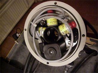
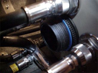
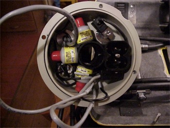
Here the inside of the scrubber lid. If you want to know the cell numbers you could take a short look at: cellnumbers. What we want to do is to check the cells on closed pressure balancing holes (PBH) and to make a small 2 mm hole in the red caps. The purpose of the holes is to be sure the pressure is equalised on both sides of the circuit board.

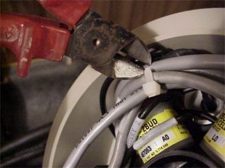
First of all we have to prepare the inside by making access to the cells. I preferred to cut the Ty-rap for maximum space.

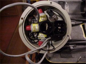
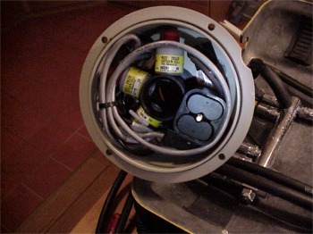
Now there is a better view in the lid. I took out the batteries for safety reasons. When the wiring is manipulated I think it is better to have no current.

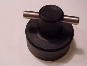
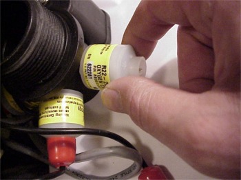
Now we need the nice standard equipment delivered with the inspiration, to unscrew the nut on the top of the scrubber lid.

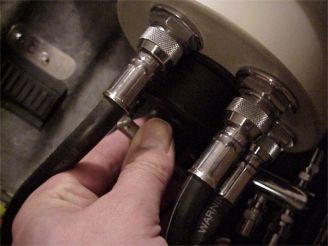
Here it is, take care that you place the tool very tight to the ring to prevent damage. You do not need to block the cell holder on the inside.

Now turn left for unlocking the ring. (CCW)

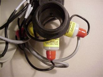
Now you can gently take out the cell holder and see the components. 
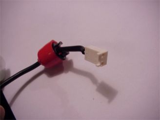
Gently pull the red cap from the cell

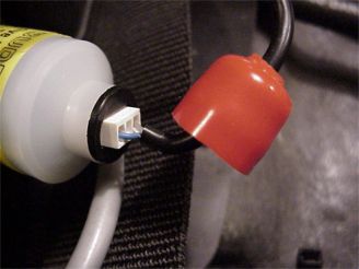
Now pull the black connector lock

And finally pull the white connector from the cell

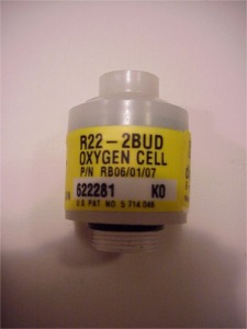
Now you can unscrew the cell by tuning left (CCW)
Check your cell on type and serial number and write it in your logbook. THIS is the moment to start your cell registration!

Here is the cell shown on the connector site. The blue arrow points to the pressure hole. As you see this one is open and fine.
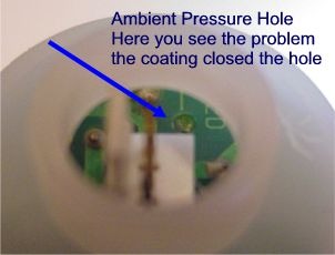
Here you see the same cell, but on the other site. Here you see the problem, the hole is closed with the coating. As Martin wrote it could only cause a problem with both holes closed, I prefer both holes opened so I decided to arrange this.

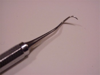
I have a very nice tool, a present from my dentist. This tool is very capable to punch the small hole and solve the problem. APD advised to sent the cells back when both holes were closed, but in my case only one hole was. If both holes are filled with the coating I would choose to sent them back.
Here you see the cell with the punched hole.

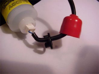
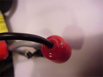
Now we have to make a hole in the red caps to let the air equalize.
Here a warning is at his place. Take great caution to not damage the wire to the cell. I bend the wire away from the 2 mm drill, so if it would punch through with force, it would not damage the isolation.

That's done
Here you see the result. Be sure the hole is clean and you should be able to see through.

OK, now replace the cell and the red cap, and repeat these steps for cell 2 and cell 3.

Before replacing the cell holder check the solenoid wiring and take care that the wire is in parallel direction of the gas addition.

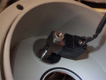
Here you see a detail of the inside of the scrubber lid. Before replacing the cell holder, be sure that the O-ring is in place. Also here is seen that the cell holder will only fit in one way because a quadrant of the fitting is edged.
Now gently replace the cell holder. Let the wiring point outside the unit. Gently turn the cell holder till it snaps into position. Now replace the locking ring. Don't forget the blue indicator.

Finishing this check, you rearrange the cabling and punt a new Ty-rap®. Replace the batteries and check functionality.


Top of page

Please sign my Guestbook