| UPDATE: Yesterday I received an email from Mr. Charles Daigneault. I opened his mail that had attachments. I could hardly believe my eyes! Lodner Darvontis Phillips was REBORNE! Mr. Daigneault managed to draw the atmospheric suit so realistic that It is hard to believe he managed to draw this all from a patent drawing! I added all 19 pictures to this web and the letter Mr. Daigneault added. I am sure everyone who likes these suits will be very pleased to see this fantastic drawings! Mr. Charles Daigneault, I am honered to have your artwork on my web! 18-2-2011. Please click HERE to go to the artwork! |
 |
|
This photograph is believed to be that of Lodner Darvontis Phillips Picture published with permission of P.A. Gruse Harris, author of Great Lakes First Submarine Library of Congres number 82-073727 |
|
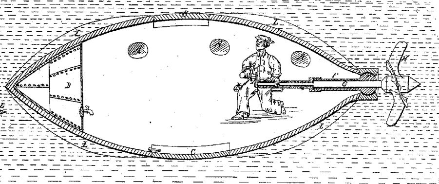
Besides his diving suit Phillips constructed a submarine that was
hand-driven by means of a crankshaft.
Another submarine was tested to a depth of
He sold the submarine. The new owner however, was found drowned in
his submarine in the company of his dog.
Phillips had offered his inventions to the Royal Navy.
However, they twice turned down his offer.
This made Phillips decide to stop the construction and designing of
submarines.
There is no certainty as to whether the second submarine that he
designed has ever been built and if it could indeed stay under water
for 20 hours. |
 |
 |
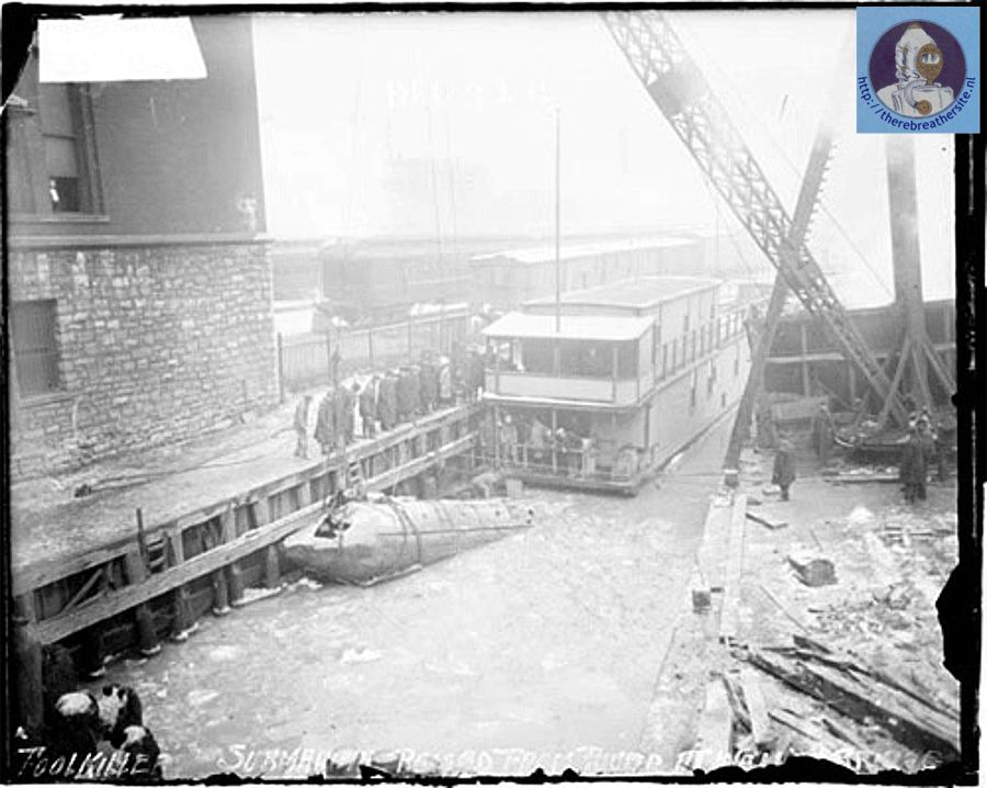
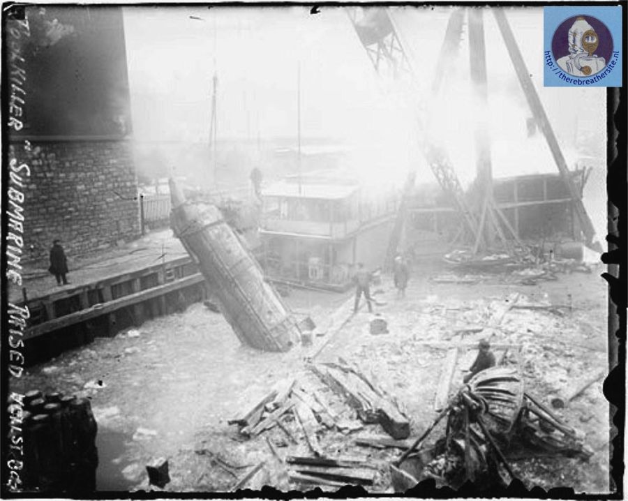
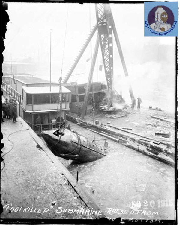
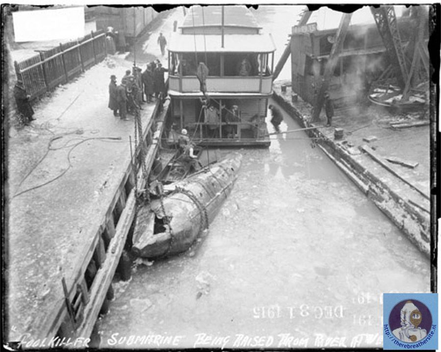
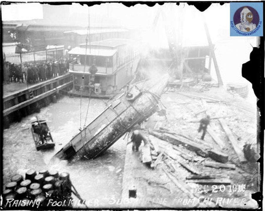
| In the Chicago Daily News archieve there are some photos showing a submarine that could have been a Philips design, but there is no clear evidence.... the pictures are beautifull, so please enjoy. If you have more information, please let me know! |
 |
 |
 |
 |
 |
|
Apart from diving related inventions Philips also designed other
products. For example he designed a hose coupling (US. Pat. 16450)
and a trowel ( US. Pat 16021). However,
these are less important to me.
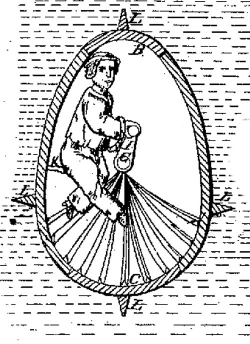
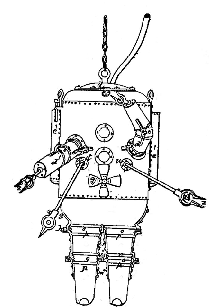
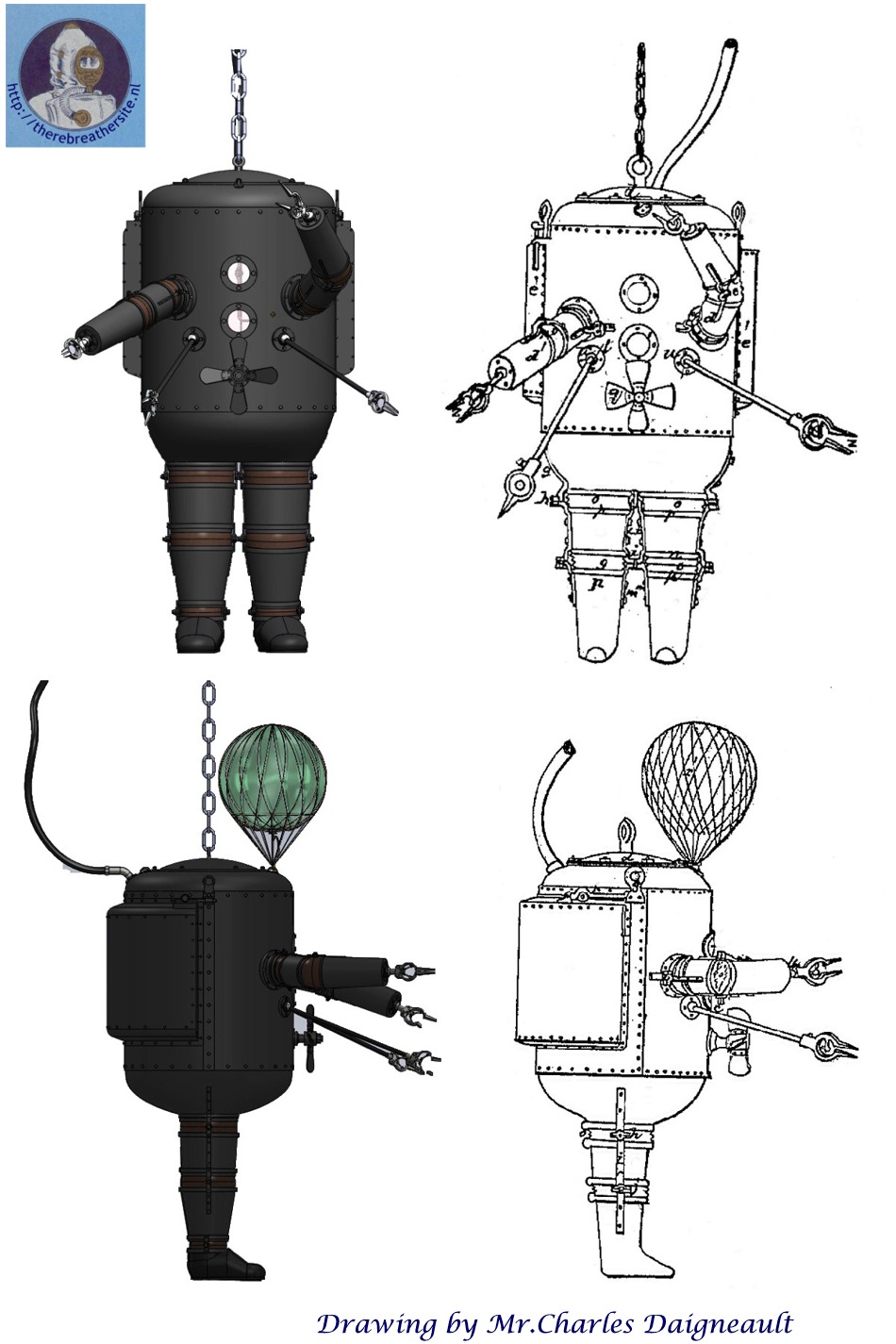
Lodner Phillips designed an atmospheric diving suit where we see the
ball and socket joint applied for the first time.
This makes the design unique and very modern for it’s time.
In various descriptions you will find many elements of his diving
suit, although many descriptions are incomplete or not very precise. |
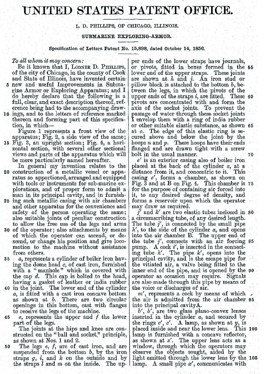
 |
|
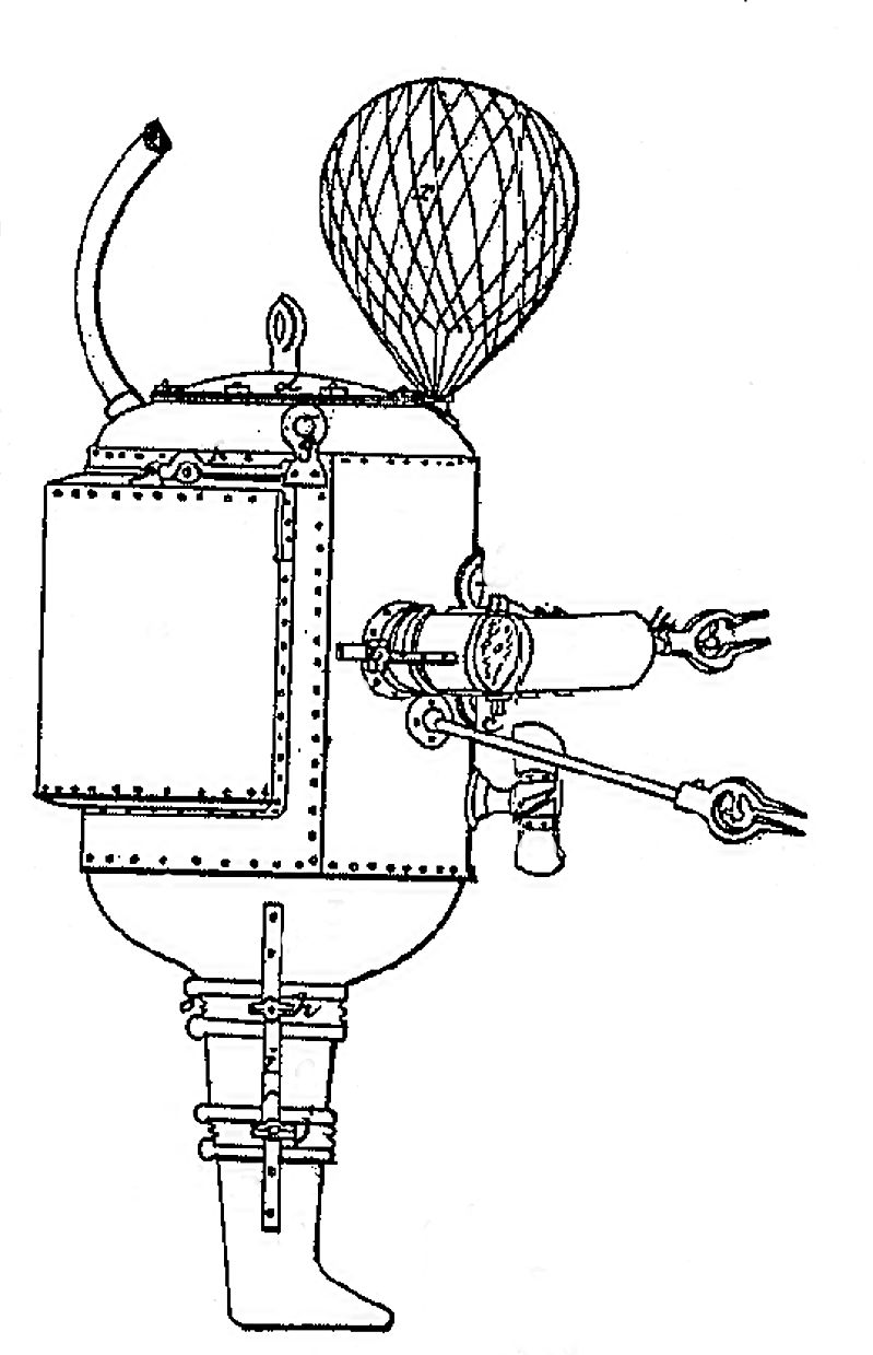
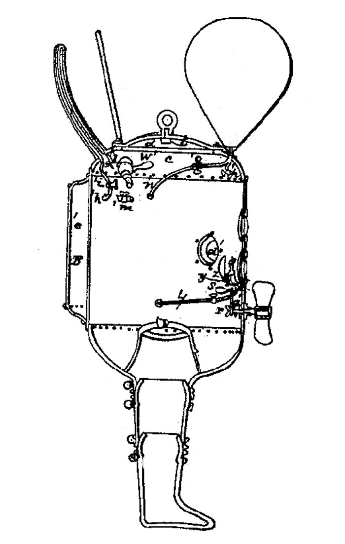
Phillips’ atmospheric diving suit is partly made of steal and partly
made of cast iron.
On top of the suit there is a bolted lid that is to be closed with a
leather or india rubber gasket.
|
 |
|
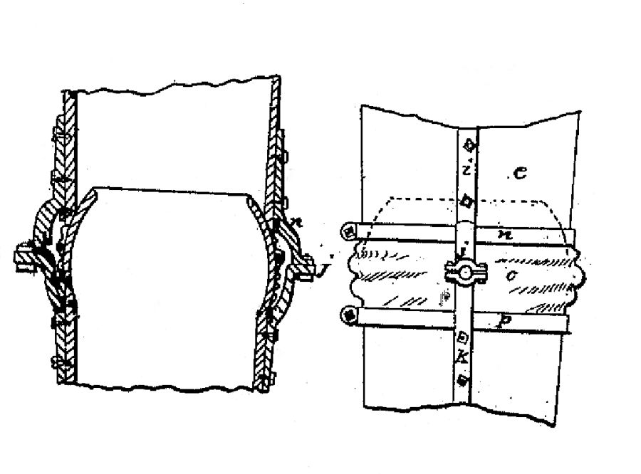
The joints were enveloped by a rubber ring secured above and below
the joints by hoops.
These hoops had their ends flanged and were drawn tight with a screw
bolt in the usual manner.
At the back of the suit a concentric formed cylinder is installed.
This cylinder is made from boiler steel.
This cylinder can contain highly compressed air.
This compressed air cylinder is in many descriptions unjustly
referred to as trim vessel.
The suit has a double hose that has a pressure resistant shell.
At the surface a pressure pump was used to transport air to the
suit.
The return hose was also used to send sound signals to the surface,
one could shout from the suit to the surface.
At the front of the suit there are two plano-convex lenses.
The upper lens is serving as a window for the
suit-operator/diver????
The lower lens has a gas light behind it.
This gas light uses oxygen that comes from the back placed
cylinder/vessel.
The suit is equipped with joints on the hips, knees, shoulders and
elbows.
The shoulder joints move in horizontal direction and the elbow
joints in vertical direction.
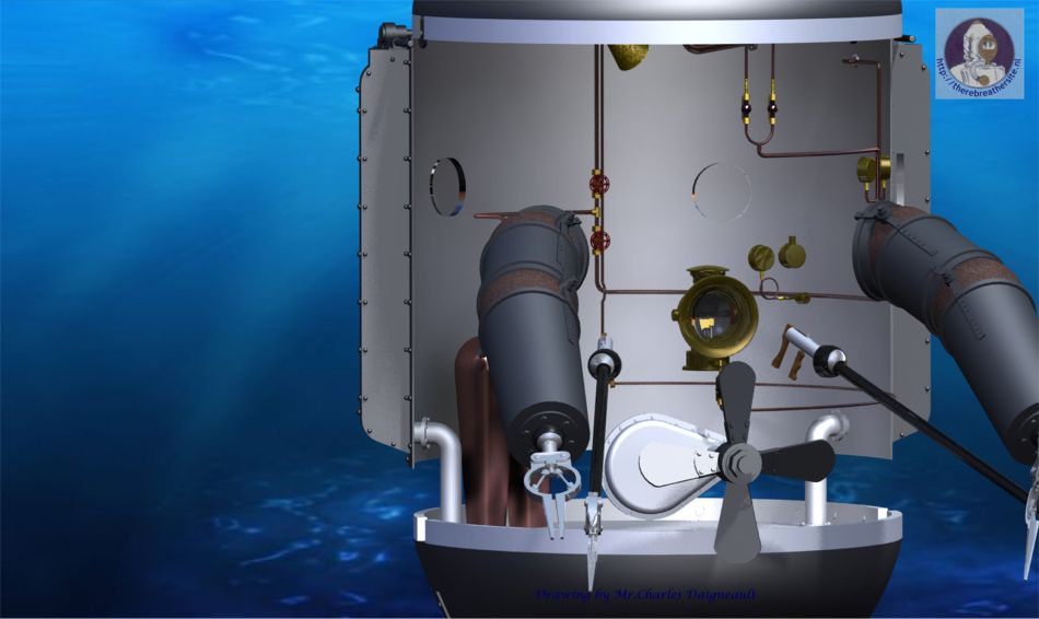
At the front of the suit is a propeller for the purpose of
impulsion.
The suit was hand-driven. In case the propeller got stuck, the
operator could unlock it via a hollow axis in the inside of the suit
und thus disconnect the propeller from the suit.
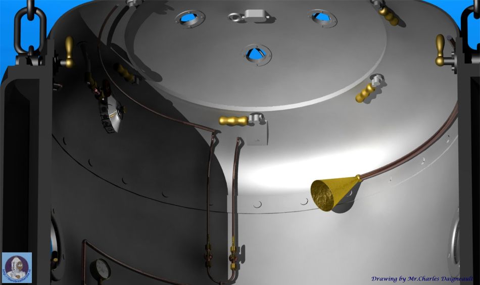
At the top of the suit there is a depressurizing valve.
At the left-hand and right-hand side there are two lifting eyes in
order to manoeuvre the suit with a rope or a chain.
At the top a central eye has been placed which can be used to lower
the suit in the water.
In it’s inner circle this eye has a construction that allows the
diver to disconnect it from the suit in case of an emergency.
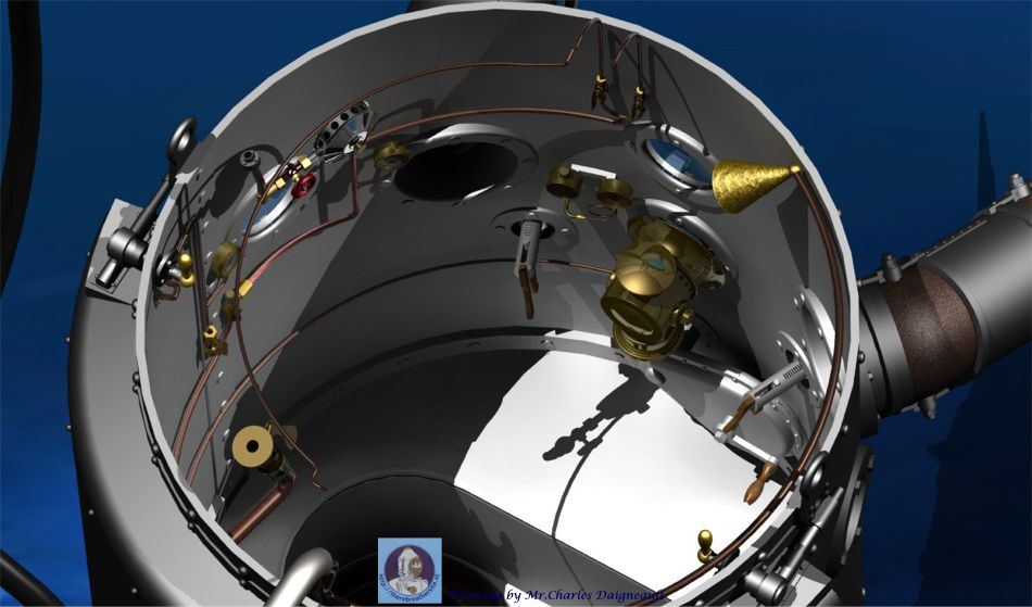
Inside the suit a small metal inhalation tube is present. This
enables the operator to breath when at surface.
The tube has to be pushed outside for this purpose.
The operator is hanging in a leather jacket inside the suit and is
strapped in so that he can develop strength in his movements.
The arms have grippers that can contain various tools.
This tools are being operated from the inside out by operating
handles.
The operator takes up his position in the suit and is being sunk
down to a certain depth.
If he wishes he can let in additional air from the supply that is
present in the cylinder on his back.
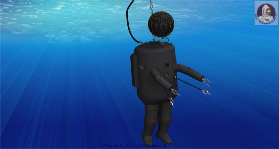
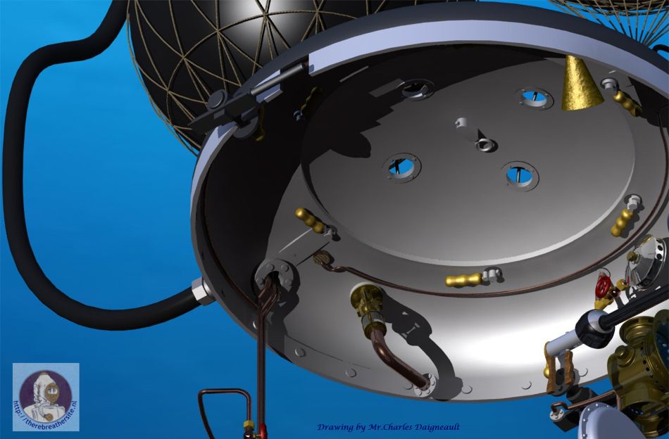
Should he so desire he can ascend independently. He can inflate a
balloon that is on top of his suit via the cylinder at his back,
thus enlarging his lifting ability and his ability to ascend
autonomously.
If this suit was ever made or
it was ever used
remains unclear to date.
The way this suit was designed would make it hardly possible for the
joints to move under high pressure.
Remarkable for it’s time is the use of joints and the great
attention for the safety of the diver.
Since it is suspected that diving suits could not reach depths much
deeper than 30-
Finally Phillips is an inventor who had much knowledge of buoyancy
systems since he designed various submarines that were factually
built. |
 |
 |
 |
 |
| You can read or study the complete patent 15898 here. |
 |
 |
 |
|
Literature:
There is a fantastic book written by Patricia A. Gruse Harris called
“Great Lakes First Submarine” L.D. Phillips, “Fool Killer” copyright
1982, library of congress Number 82-073727
|
| A special thanks to Patricia A. Gruse Harris for her kind cooperation and hard work collecting all data about Phillips. |
| All pictures information or other information related to Lodner Darvontis Phillips is most welcome! |
| added 26-6-2009 this article from the Cleveland Plain dealer |
 |
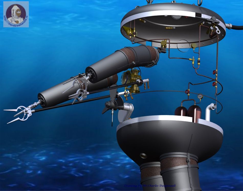
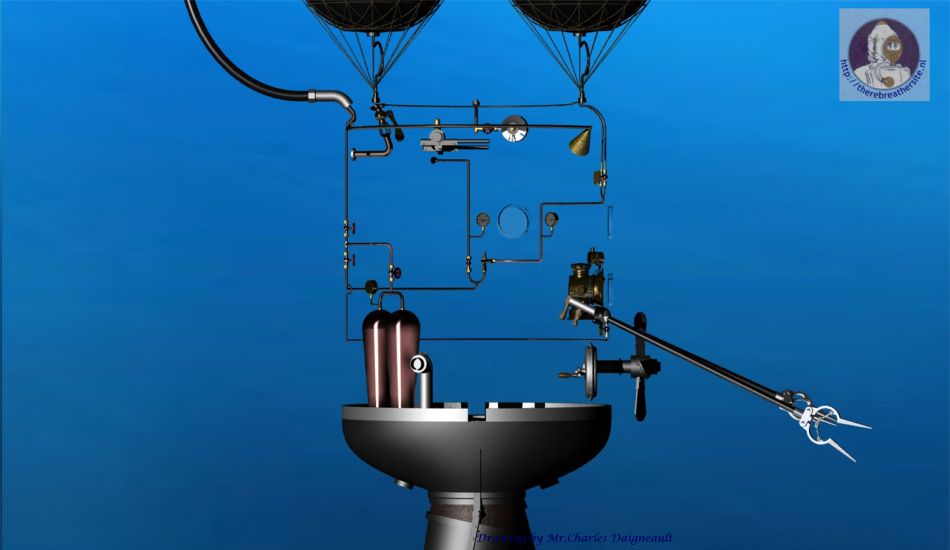
| Charles Daigneault's ART WORK |
|
Dear Mr. Bech
It has been a
long time indeed, but as promised, I have prepared a new 3d model
for therebreathersite.nl historic
A.D.S.
section, so attached you will find some images of the Lodner Philips
rig. I must confess I chose Mr Lodner Philips design because I
thought at first it
would be an easy assignment, after all, what is difficult in a
cylinder with arms and legs.
boy was I ever wrong! What was supposed to be an easy model
turned into a long term research project and an incursion into Mr.
Philips imaginative mind. I could not be content with a simple
reproduction of the patent drawings. I asked myself what if they did
really built it? In a leap of imagination I wondered
how would this design turn out if a late Victorian top-of-the
line craftsman had picked up Mr. Philips patent and actually built a
working prototype using 19th century
boiler and steam engine technology? I got engrossed in the
idea and started modeling what might have been.
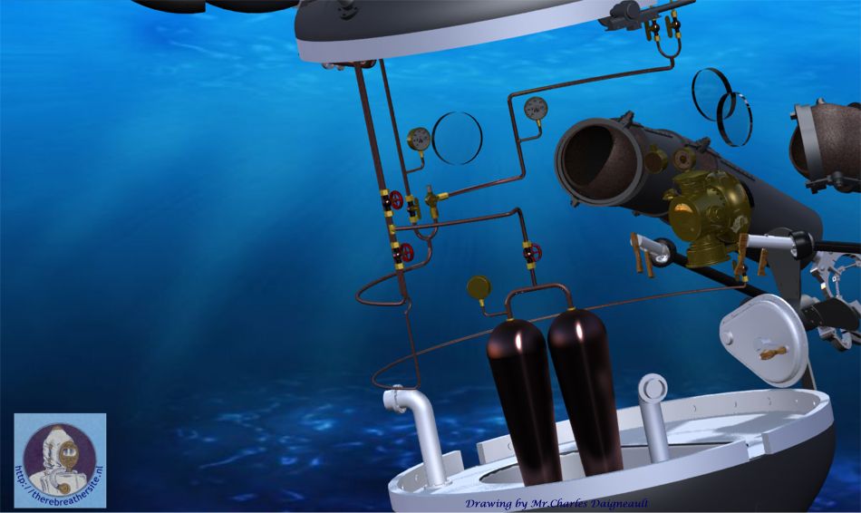
Mr.
Philips was a precursor, his design had some features that are still
in use today in state-of-the-art underwater technology like
thrusters, high intensity lighting, inflatable lift bags,
communication apparatus
and manipulator arms. Unfortunately he seems to have lost interest
in the middle of his design process and rushed to finish his
drawings leaving
numerous details
vague, abset or unexplained. Also I had to face the same
challenges he did to design a practical a.d.s. While in the process,
I realised the numerous
technical difficulties that needed
to be overcome
for such a design to become (maybe)
a workable diving
machine instead of being a gruesome death-trap.
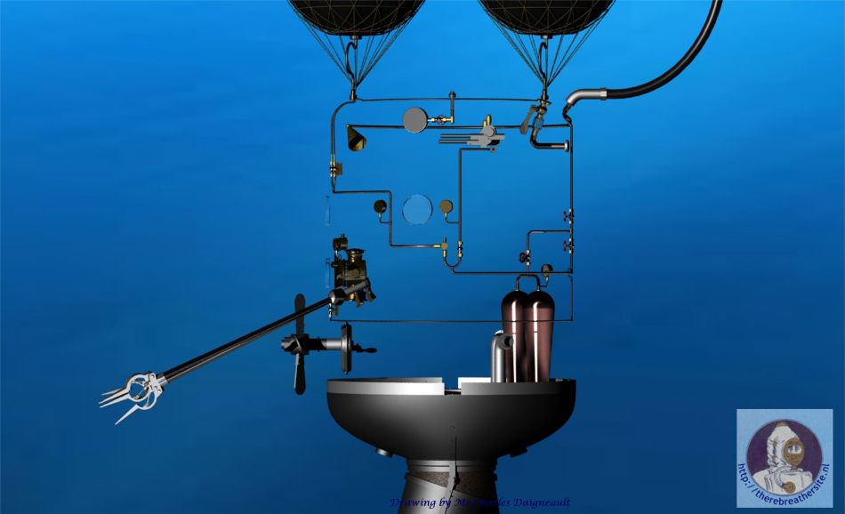
Some failings became immediately evident,
the most obvious, being
because the shell
is basically an empty cylinder, it would never had been able to
submerge, it would simply have flipped on it’s side and floated away
thus the need for ballast, the incomprehensible backpack took a new
meaning under this assumption, I think it would have proved
inefficient as a compressed air tank, so turn it into a ballast tank
and put period “air flasks” inside and also turn the whole lower
portion, the large “pants”
into part of a
complex dual ballast system with intake, fill control valve and
compressed air purge valve. The lamp would have used acetylene, not
oxygen, the gas being
fed from the surface, looks very dangerous thought,
and there is the strong possibility, the diver/operator might
have cinged his beard while looking out the upper porthole! A part
reference number on the front patent drawing left side relates to he
incomprehensible device located on the top of the backpack right
side, I concluded this is a lock-release for the right and left side
lift hooks, the builder might have realised it was not such a good
idea to lift the heavy machine by the hatch cover only, better use a
spreader bar
for hoisting even if a center lift eye watertight lock-
release is provided , and
while we are at it, provide latch dogs in the inside so the operator
can exit in case of the inevitable emergency, and two side-looking
and top cover portholes , the necessity of which
Mr. Philips seems to have overlooked. Also add a spur gear
and pinion to the propeller for efficiency.
. Now
because of the work done by hardhats divers
in deep-sea salvage and also
by bridge construction
workers during the 19th
century, our Victorian era engineer would have had an inkling of the
problems related to pressure and pressurised environments, thus
an automatic pressure
regulator with manual override is fitted to maintain a 1 atmosphere
relative pressure. A
“Christmas tree” manifold with spherical valves is to be used to
manage compressed air between the air tanks and surface feed,
pressure is further used for lift bags and ballast purge. Now about
the watertight
articulated joints, the vague
patent drawings clearly shows they would never have worked as
designed. This
A.D.S.
is
destined to become a rigid
observation tower under a few
meters, except for the manipulators which might have been
usable, unfortunately the
water-proofing technology necessary to accomplish this, like
o-rings, was not yet
invented, so every joint would have leaked badly, even with the
addition of a bilge pump, it is evident the whole rig would have
proven unusable, but as this is an imaginary prototype, let’s
provide spherical and rotary watertight joints along with the
reinforcing hinges to attain some degree of mobility. What about the
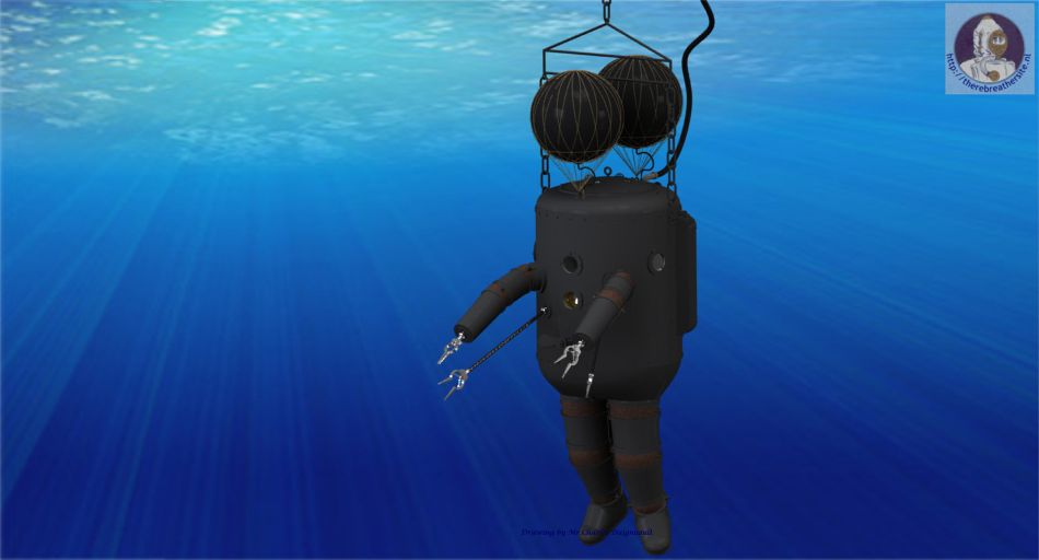
annoying lift-bag? Well maybe our engineer would
have installed two
instead of a single one and controlled
them separately for inflation
and deflation, maybe a skilled diver would be able to tilt front to
back by adjusting the bag’s air pressure differently with two
separate valves and purge, finally depth and air pressure gauges
would complete the fittings of this primitive device. All that is
missing is a CO2 scrubber and you have a 19th century
a.d.s! After completing this project, I was left with many
unanswered questions, Which is perfectly normal when dealing with a
concept that is over 100 years old! In all, it was for me an
interesting and fun experience. I am sending you some .JPG shots of
the resulting model, I would be honoured if you decided to post
them on your website. I
also added some “artsy” illustration type renderings in art deco
style, but I am not sure they have their place on
therebreathersite.nl I
included them mainly for your personal enjoyment.
Unfortunately I was unable to
produce a satisfactory .AVI file, the results proved
very disappointing , In the future I will have to use a
different software than
Solidworks
for this purpose to obtain an enjoyable and realistic animation.
There you have it Mr. Bech,
It took some time but I did it, now I have to move on to
another project, but I plan to make another
historical a.d.s. model in the coming months,
I already decided which design I am going to tackle, but this
is another story. In finishing, thank you very much for giving me
the opportunity to interest you in my work. And I will, of course
continue to explore and enjoy your
great web site.
In the meantime,
all my best wishes to you Mr. Bech.
Cheers.
Charles
Daigneault. |
 |
 |
 |
 |
 |
 |
 |
 |
 |
 |
 |
 |
 |
 |
 |
 |
 |
 |
 |
| Thank you very much Charles! Highly appreciated!! |
| Please sign my Guestbook |
| Email: jw.bech@quicknet.nl |
Lodner Darvontis Phillips
(1825-1869)
Lodner D. Philips was a man of varied talents.
In his day and age he was known as one of the best under water engineers.
He built a number of submarines and designed one that was steam-driven.
He was a shoemaker from the
In 1856 he designed an atmospheric diving suit (ADS) for which he was granted a patent.
Menu Atmospheric suits
Updates
Speedmenu
Search page
Webshop
Home
GO BACK TO
ATMOSPHERIC
DIVING SUITS.
Mainmenu:
Search this Website
Information about RB
Photo galleries
Historical Information
Links & Downloads
Reviews
Homebuilders
Electronics
Updates, speed menu
Web shop
Reviews SC rebreathers
Reviews CC rebreathers
RB’s through the ages
Inspiration rebreather
Database Oxygen RB’s
Database Semiclosed RB’s
Updates
Speed menu
Search this web