|
THE DESIGN OF THE ELECTROLUNG
BY
Walter Starck
July 1998
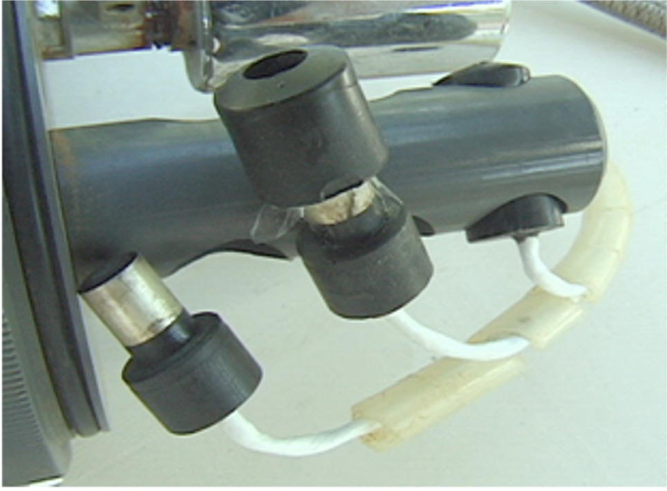
I Sensors
The Electrolung used
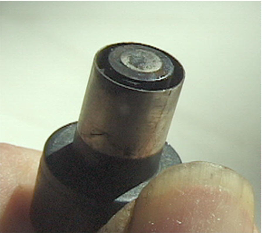
three polariographic oxygen sensors. The sensors were robust
handmade ones we made ourselves. They had a central platinum
cathode about 1/4" in diameter surrounded by a concentric silver
anode about 3/8" Diameter. In between was an annular groove for the
KOH electrolyte. A .001" teflon membrane held in place by a thick
silicone rubber boot retained the electrolyte. Although the sensors
would run for weeks before desiccation of the electrolyte became
limiting our SOP was to make them up fresh and calibrate them for
each days diving. At the end of the days diving the membranes would
be removed and the sensors washed with distilled water. Making up
and washing off the sensors only took a few minutes and assured you
always had fresh sensors.
Sensors of this type
don't wear out so they were hard wired into the circuit. Unlike
galvanic sensors they don't use oxygen but rather just respond to
its presence. They work equally well submerged so the effect of any
condensation is negligible. A drop of water fully covering the end
of the sensor would only slow the response time. It practice we
never had any condensation in the sensor area as this came
immediately after the canister so the gas was at its warmest and
driest point in the circuit. Thick plastic walls probably helped
too in avoiding condensation on cold surfaces.
The chief advantages of
the sensors were that they were always fresh and condensation wasn't
a worry. The disadvantage is that in making them up with fresh
electrolyte you can screw up by contaminating the sensor via sloppy
technique. Any significant change in calibration after a fresh make
up would be an indicator and determining why should be mandatory
before proceeding further. Still, there are the black box
mentalities who will simply crank the trim pots until they get the
reading they want and then assume all is well.
There were two trim
pots for calibrating each sensor. One for zero, the other for gain.
Zero was checked each time before the sensors were made up. Gain was
calibrated initially with air then the unit was put together and a
check with pure O2 was done. The permeability of Teflon to O2
varies with temperature. The sensors were of potted epoxy
construction with the electrodes embedded in the epoxy. A
thermistor in contact with the
underside of the
cathode was also embedded. This thermistor had a similar response
curve to the teflon and compensated for the temperature effect
keeping output linear over the desired range. Our chosen set point
was 0.5 Atm PPO2. The bottom line was that with proper care the
sensors were very reliable. Enough so, that they could be hard wired
in and I know of no case where one ever had to be replaced.
II Electronics
(control, readout, alarm)
Unlike galvanic
sensors, polariographic electrodes don't generate electricity.
Rather, the conductivity of the cell varies in the presence of
oxygen. A bias potential from an external source is applied between
anode and cathode and the resulting flow of current is a function of
the molecular concentration of oxygen present. The current
involved is very small so an Op Amp is used with each sensor to
boost power to a level useful for control and monitoring.
Hermetically sealed trim pots which incorporate an O-ring seal
around the adjustment screw provide for zero and gain adjustment of
each Op Amp thus enabling calibration.
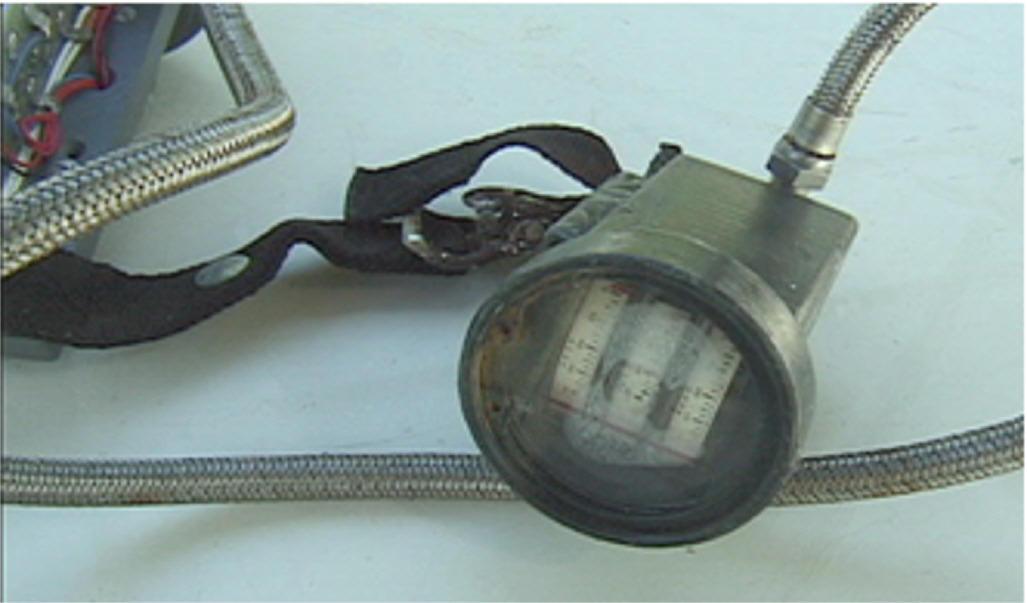
The amplified signal is
read out to a wrist display, consisting of a stack of three edgewise
panel meters. 100 microamp meters were used in conjunction with
high resistance to prevent a possible short in this circuit from
affecting the solenoid control. Mil Spec, so-called "shock
resistant" meters were used. These resist minor bumps but still
they won't stand up if you drop the display on a steel deck or
concrete. In practice it wasn't a significant problem but
occasionally a meter did require replacement. This was quick and
easy to do.
The big advantage of
this type of analog display is, that you can tell at a glance
everything you need to know. In use all you need to verify is that
all of the readouts are in line with one another and at or a bit
above the set point which was exactly mid scale. This kind of meter
is also precise enough for calibration purposes. If I were doing it
today I would look at bar type LCD or LED readouts for monitoring
and perhaps a separate switchable numeric display for calibration.
I would also seriously consider a miniature head up display in the
mask instead of one on the wrist. I don't like numeric displays for
monitoring as they entail reading and mentally comparing numbers
which requires much more attention than just noticing if position
and alignment are where they should be. Possibly some of the
commercial RBs have already done all this.
The amplified signals
from all three sensors were fed into a fourth Op Amp which in effect
averaged them and used the resulting value to control the solenoid
set point via a switching transistor. We used a fixed set point of
0.5 Atm PPO2 but it would be simple to add a trim pot to provide an
adjustable set point. Clipping circuitry limited the input to the
control Op Amp from each sensor to values corresponding to 0.25 and
0.75 Atm PPO2. If any one sensor began to read drastically different
from the others its effect on automatic solenoid control was thus
limited. Clipping came after the meter display thus they would
continue to read true output even if the input to the control Op Amp
was clipped. Clipping also activated an audible alarm. If the
alarm sounded a glance at the meters would tell you what the
situation was. If only one was off the other two would continue to
exercise control. If all were high, low or different from one
another you could use manual control while aborting the dive.
The Op Amps require a +
and a - voltage power supply. This was supplied by a pair of 9V
Manganese Alkaline transistor radio batteries. Bias to the sensors
was provided from the same source via a voltage dividing resistor
circuit. A second pair of the same batteries provided switchable
backup power. A third pair used in parallel provided separate power
for the solenoid. The solenoid did not have backup as this is
non-critical because manual control of O2 is easily effected. The
snap terminals used for this type of battery were securely attached
to a bulkhead. A screw adjusted base plate held the batteries
firmly in place and against the terminals avoiding any possibility
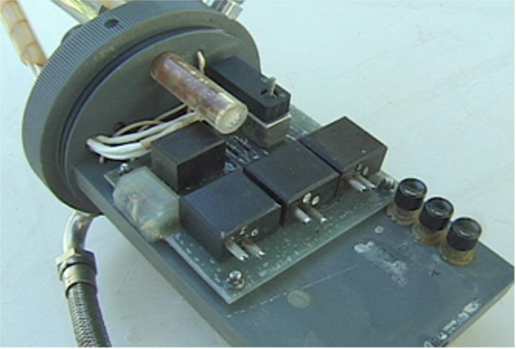
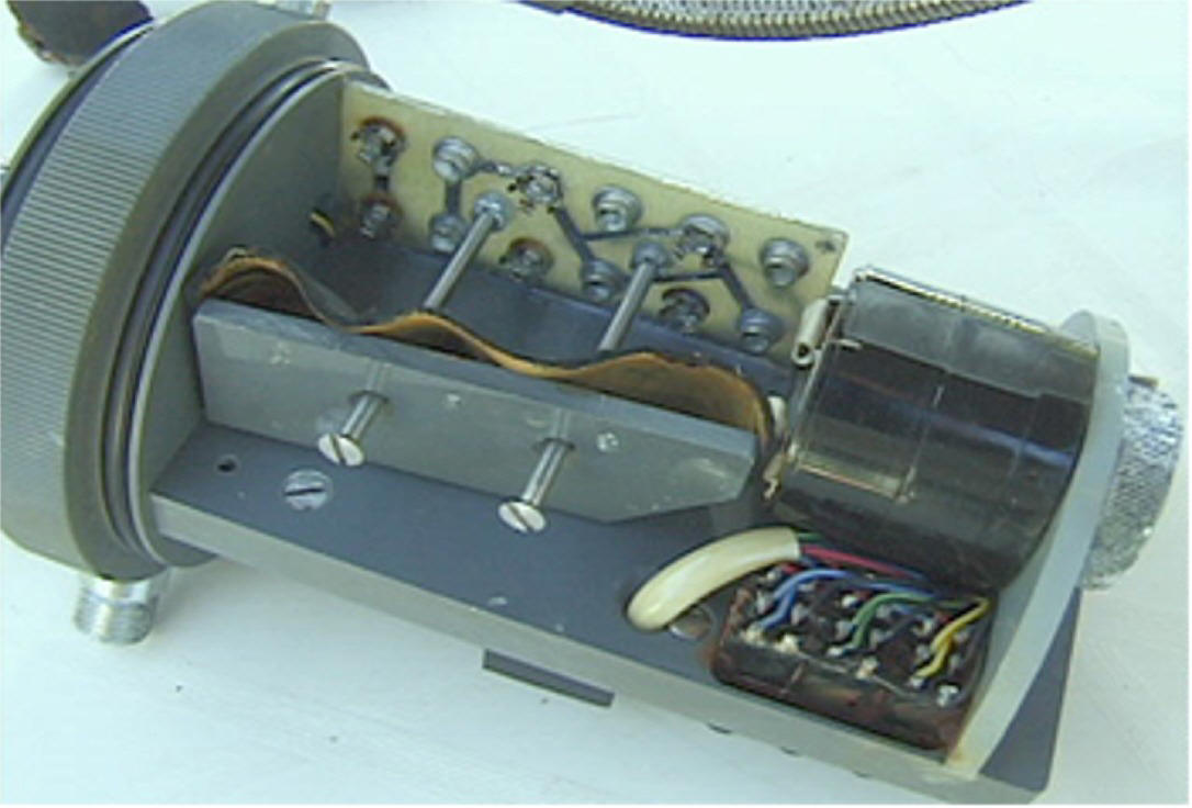
of a loose battery connection. All the electronics were incorporated
on a single circuit board about 4x5". This was mounted on one side
of a longitudinal bulkhead in the electronics housing with the
batteries and audible alarm on the other. This longitudinal
bulkhead was itself mounted on a transverse bulkhead which separated
the electronics compartment from a plenum above the absorbent
canister. The solenoid and sensors were mounted on the opposite
side of this transverse bulkhead thus everything electrical other
than the wrist display was immediately adjacent to each other.
In the units I made all
of the electronic components were on a printed circuit board. After
assembly the boards were coated with a spray-on waterproofing
compound as is widely used for marine electronics. At Beckman the
components were assembled into 4 micro- welded epoxy potted modules
which plugged into gold plated sockets on the circuit board. In
theory this is a better way to go but in practice it didn't make any
noticeable difference.
With respect to
reliability of electronics in this kind of application. Recently
someone posed the question of when was the last time your TV failed
to which Robert made the wonderful reply, "The last time I took the
bastard underwater." Both comments reflect important points.
Electronics in themselves can be extremely reliable. In terms of
MTBF, far more reliable than most mechanical devices. Enough so
that they can be trusted for things like passenger aircraft control
systems where thousands of systems are in everyday use and a single
failure means the loss of hundred of lives. But Robert is right
too. If you flood them with water they fail. The problem then is
really a mechanical one. Can electronics be reliably enclosed so
as to prevent flooding in underwater use. If it were solely a
matter of constructing a watertight pressure proof housing for the
electronics that alone wouldn't be too hard. Unfortunately there is
also the matter of connections for sensors, displays, a solenoid,
and a switch plus keeping all these external devices themselves
dry. The possibilities for leaks begins to multiply. With a great
deal of care in construction and use, high reliability is achievable
but I think there is a much easier way to reliably keep out the
water.
The key to the solution
is pressure. Keeping things watertight under 100-200 psi is
difficult. Doing it under 0.5-1 psi is easy. In the Electrolung
everything was at ambient pressure. The electronics compartment was
vented via a small canister of silicagel with the rest of the
system. A standpipe for the vent orifice prevented any accumulated
moisture in the canister plenum from being pushed into the
electronics compartment. In anything but a head down position the
electronics were above the counterlung thus any leak would normally
result in gas escaping rather than water coming in. In practice
with the kinds of seals involved and the very low pressure
differentials leakage anywhere in the electronics section was never
a problem.
III Gas supply
Two, 9 cf., 2100 psi steel
gas cylinders were used for O2 and inert gas. These were lightweight
models FAA certified for use in aircraft. Initially we used chrome
plating to protect them, later we went to teflon coating. Beckman liked
the more military look and there was some concern over possible hydrogen
embrittlement from the chroming process.
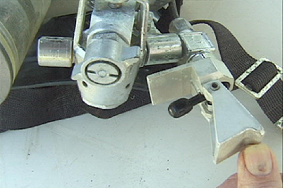
Standard,
old style, "K" valves were used as cylinder valves. On the inert
side a SCUBA regulator-type yoke was used to mount a high pressure
1/8" NPT needle valve operated by rotary action of a T-shaped
handle. Inert gas was valved in manually directly from the tank as
needed using this valve. In use it had a very smooth precise feel.
Inert gas was valved into the plenum at the bottom of the absorbent
canister so that some mixing would take place before it got to the
sensors.
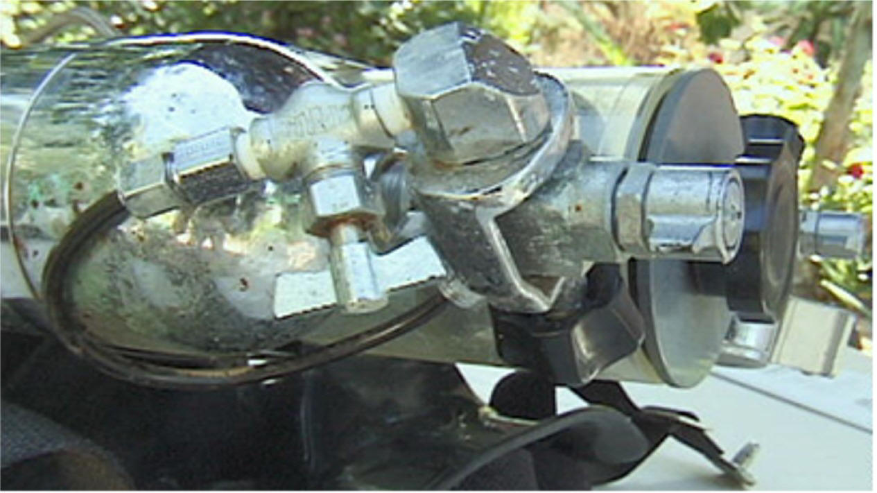
On the O2 side a piston
type first stage of a U.S. Divers single hose regulator was used to
reduce tank pressure to about 60 psi. This is somewhat lower than
such first stages normally deliver and was achieved by using a
weaker piston spring. The normal hose to the second stage was used
to connect the O2 supply to the solenoid valve. The octopus port of
the first stage was used to attach an O2 bypass valve. This was a
spring action, lever activated low pressure valve and it was
protected by an enclosure which required opening a spring closed
cover to get at the valve. The manual bypass valved O2 directly into
the sensor compartment so the result was immediately readable.
I will digress briefly
on O2. In addition to the physiological risks recently discussed in
some detail on the list there is also the danger of fire and
explosion. Valves, regulators, fittings and any other equipment
used for O2 have to be thoroughly degreased of any petroleum based
lubricants. If lubrication is required, as for example with the
o-ring seal
of a regulator piston,
non-combustible silicone based lubricants must be used. Be aware
that even a fingerprint oily with suntan lotion can start an
explosive fire with O2. Once an O2 fire starts all sorts of things
you might not ordinarily think of as combustible burn ferociously.
I have heard stories of chamber fires in which everything inside,
including the occupants, was reduced to ash.
My partner Kanwisher
was on one of the advisory panels to NASA in connection with the
Apollo program. Although he recommended using a mixed gas
atmosphere in the Apollo capsule he was over-ridden by the engineers
who felt that monitoring the PPO2 was too difficult. John knew
better as he had been doing it for several years in conjunction with
his work on respiration but the engineers prevailed. The result was
the fire which killed three astronauts.
The solenoid valve we
used was a miniature 12 volt one made for pneumatic control. We
equipped it with a miniature screw adjusted needle valve outlet.
When the setpoint is reached and the solenoid is triggered it takes
perhaps three or four seconds for the sensors to respond and rise
enough to cut it off again. The solenoid needle valve was adjusted
so that the O2 injected raised the PPO2 to a peak pulse of about
0.75 Atm and would usually
trigger a couple of
beeps from the audible alarm. Within a couple of breaths mixing
brought the level back to perhaps 0.65 after which it dropped more
slowly as it was consumed by metabolism until the setpoint was
reached again after about a minute or so. That would be for
moderate activity such as easy swimming. At complete rest it would
of course take longer to drop back to the set point and less time if
you were actively swimming.
If the needle valve was
adjusted to a lower flow rate solenoid activation would be more
frequent and of longer duration placing an unnecessary drain on the
solenoid batteries. If much higher flow was adjusted for the O2
spikes would be too high and the alarm would be sounding much of the
time.
I think there are now
smaller, more power efficient solenoid valves available.
The solenoid and manual
bypass valves were of the downstream type so that if high pressure
leakage from the regulator occurred it would release when it reached
the level where it overcame the spring tension which normally closed
the valve. This is important to prevent either valve lockup or
blowing out the supply hose in the event of a high pressure leak.
In the event of O2 leakage from either valve the cylinder valve
could be used to cut it off.
The gas cylinders were
mounted on either side of the central larger cylinder containing the
absorbent canister and electronics section. This assembly was worn
as a back pack with the valves at the bottom at hip level. Inert gas
had to be added several times on descent and at other times if you
lost any from nasal exhalation. Manual O2 was normally only used in
decompression. The inert gas valve was therefore on the divers left
side leaving the right hand free for more complex tasks. Swapping
sides for southpaws would have been easy but I don't recall anyone
ever raising the question. It was no big thing either way.
IV The breathing
circuit (mouthpiece, hoses, counterlung, canister)
The Electrolung
mouthpiece was originally constructed of PVC. The main body of the
mouthpiece assembly was made in three parts fuse glued with PVC
solvent cement. At Beckman this part was manufactured as a teflon
coated aluminium investment casting which made a nicer looking
part. A rotating drum type valve operated by a small lever
permitted closure of the mouthpiece if you wanted to take it out of
the mouth underwater. Two check valves directed gas flow to the
proper hoses for inhale and exhale cycles.
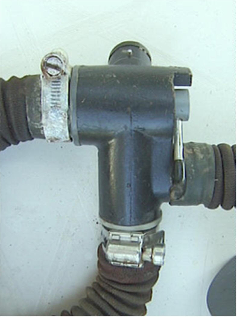
Three breathing hoses
were attached to the mouthpiece. One went straight down to the
counterlung which was worn on the chest. The other two went to
either side over the shoulders to the inlet and outlet of the
absorbent canister/electronics section which was worn on the back.
Initially hoses from the old style twin hose scuba regulators were
used. At Beckman we found a manufacture in L.A. who made high
quality fibre reinforced hoses for the O2 breathing systems in
military aircraft. The price was only a little more than the scuba
hose and they could be made to order as to length in small
quantities. Scuba hoses tended to start to leak after a year or
two. The others are still usable after a quarter century in tropical
conditions.

Hose clamps may seem
mundane but are worth considering. A hose coming off with scuba is
an inconvenience. With a RB it is a life threatening disaster.
Initially we used the spring steel ratchet type clamps used on scuba
regulators but I didn't fully trust them and they rusted. We tried
chrome plating them and found they would then break unexpectedly due
to hydrogen embrittlement. In the end we went to good quality heavy
duty SS worm screw type clamps. Some SS clamps have ordinary mild
steel worm screws which rust, electrolyse, and break after awhile in
marine use. Light weight SS clamps can also break for no apparent
reason due to stress fatigue. SS is prone to this. SS fitting used
in sailboat rigging are notorious for letting go at the most
inopportune times.
A lot of people seem to
now use the nylon ratchet type ties for clamping hoses but I
wouldn't trust these either for critical applications. Nylon is
subject to cold flow under stress and after a while they become
looser.
Using them as a back up
next to a good SS clamp however might not be a bad idea.
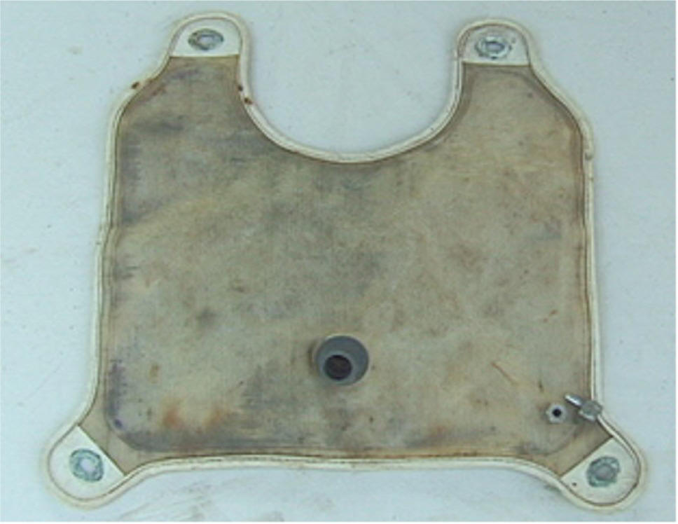
The counterlung was a
bag made of two pieces of plastic material electronically welded
together over a 1/4" surface around the entire perimeter about 1/2 "
in from the edge which was then sewn together wrapped in a heavy
edging tape. Originally I used clear vinyl for the material.This
worked well enough but later I found a lighter, more flexible,
translucent fibre reinforced plastic material which was better.
Being clear or
translucent offers two advantages. It lets light in and so reduces
the growth of micro-organisms. It also makes it easy to see if any
water has accumulated and get rid of it before it gets to a level
where it might be drawn into the absorbent canister. Places which
make awnings, boat covers, etc. or those who make plastic zipper
bags ,folders and the like can easily and inexpensively do this kind
of work. All you need is a paper pattern of what you want.
One-offs for prototyping are not expensive and with a $100 or so for
a die for the welding they can pop out small quantity runs dirt
cheap. Usually they also have samples and catalogues of all sorts
of material to choose from. Teflon coated nylon is now available
and might be very good for this application. I mention all this
because some homebuilders may be interested.
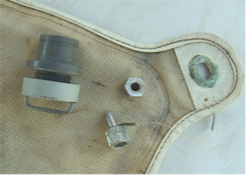
The counterlung had a
single hose attached about 1/3 of the way up from the bottom on the
front (away from the body) side. A drain plug was at the bottom
near the lower left corner. At Beckman we added an overpressure
relief valve near the top. The fittings all used a flange and
threaded collar type attachment similar to a kitchen sink drain.
The flange incorporated a groove and o-ring in its face which
ensured a firm grip and seal with the counterlung material. The
fittings were machined from PVC except for the small drain fitting
which was SS or chromed brass with a 1/4" plug on a short lanyard.
It was basically the same as a control gland used in underwater
camera housings.
The overpressure relief
valve released at somewhere around 0.75 psi. Its only practical use
was the prevention of possible counterlung rupture if gas was
accidentally valved in with the mouthpiece shut-off valve closed.
It was introduced at the suggestion of experienced OC divers who not
being used to getting rid of excess gas via the nose during ascent
tried to exhale against a full counterlung and couldn't.
The counterlung was
attached by grommets at each corner which mated with twist studs
mounted on the shoulder
straps at the top and on short adjustable straps paralleling the
backpack waist strap on each side at the bottom. The counterlung
volume we used was about 4 L.
There has been some
discussion on the list recently re: the relative merits of chest
mounted (resistance on exhale) Vs. back mounted (resistance on
inhale) counterlungs. In an earlier post, which has been quoted in
the recent discussion I opted for chest mounting as preferable
because the mechanics of breathing musculature is such that the
power available for exhalation is greater than that for inhalation.
The counter argument is that resistance on exhale reduces the volume
of exhaled gas leading to CO2 retention.
First, we need to keep
in mind all this is somewhat hypothetical and in the real world both
configurations have been used successfully. With sustained high
level exertion where any advantage might be important (and in the
continuing absence of any proper comparative testing) I would opt
for the chest mount for two reasons. It's less tiring to put a bit
of extra effort into exhaling than it is into inhaling and the
bottom line at the extreme for ventilation lies with how much gas
you can move in and out in a given time. Given equal resistance in
either direction the more powerful exhalation cycle will move the
greater amount of gas. In the end, over a few breaths, expiration
and inspiration must be equal. Restriction of either sets the limit
so if there has to be a restriction I would rather it be on the side
which can best handle it.
We sold a number of
Electrolungs to commando type users. One of their prime concerns
was breathing resistance in sustained hard swimming. After trying
it, all gave it their thumbs up in this respect. In out of water
chamber tests at 1000 FSW pressure breathing resistance during
exercise was encountered. This was in the breathing circuit itself
and could of course be relieved somewhat by bigger hoses, larger
absorbent bed cross section, etc but as the market for that
capability was effectively nil it was never pursued.
One memorable
experience with the commando types took place in the Bahamas. A
British Royal Marine Commando attached to the Canadian Navy flew
down to join me on my vessel and try out the Electrolung. He was a
big bullet headed guy, built like a fridge with a head. After a
couple days instruction diving he wanted to do a long hard swim with
it and as there was no one else to do it with him I ended up going
along. He went for a couple of miles virtually flat out. Luckily
the water was crystal clear so I managed to at least keep him in
sight. When we came to the surface the bastard wasn't even winded.
He was satisfied it could do the job and just wanted a smoke. It
was flat calm and the water was only about 30 feet deep so I had a
skiff following us with his smokes and we could ride back.. Although
I still don't know for absolute certain whether chest or back mount
is optimal I do know that chest mount is good enough. What I really
do like about it is that it is easy to see if there is any water in
it and easy to pull the plug, squeeze the bag, and expel it. We did
have a couple of experienced OC divers, new to the Electrolung, let
water leak in around their mouths until it was gurgling away with
each breath. They continued until they had largely flooded the
absorbent canister and eventually got a mouthful of absorbent
cocktail. They were quite irate about all this and swore it was the
fault of the Electrolung. This kind of thing is a recurrent problem
with RBs. Experienced OC divers have habits which don't go with RBs.
They also tend to think of themselves as expert divers rather than
as novice RB users. As a result they often don't really listen and
take advice well and tend to blame the device if anything is not
right rather than realising that they have to learn to use it right.
The actual breathing
circuit for the Electrolung was: Exhale directly to counterlung via
bottom mouthpiece hose. Inhale draws gas from counterlung back out
the same hose into left mouthpiece hose thence to the bottom of the
canister via a central tube inside it. At the bottom the gas
emerges into a plenum which distributes it over the inlet surface of
the absorbent column. After passing through the absorbent it emerges
at the top into the chamber where the sensors and solenoid are
located. From here it continues via the right mouthpiece hose into
the mouthpiece itself.
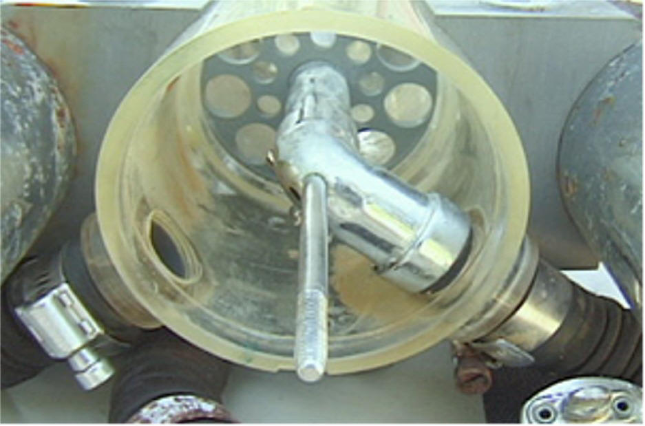
V Absorbent canister
/ Electronics housing
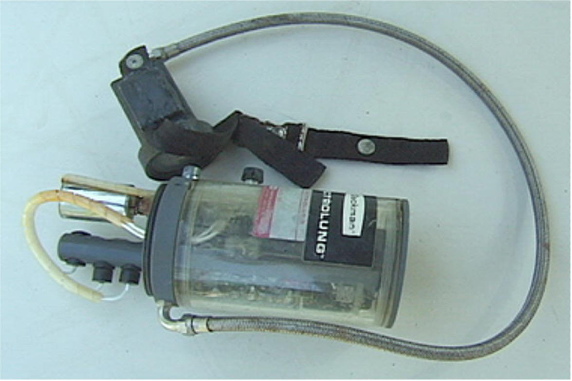
In the Electrolung the
CO2 absorbent and electronics were housed in a transparent acrylic
(Plexiglas) cylinder which together with the gas bottles was worn as
a backpack. This cylinder was 24" long x 4" I.D. with 1/4" thick
walls. It was divided into two pieces. An 18" section contained
the absorbent bed with a 4" space at the top which accommodated the
sensors and O2 solenoid. A 6" section at the top contained the
electronics. A small knob on the electronics section operated a
double throw, center off, switch controlling power to the
electronics via either set of batteries. This was reachable behind
the head if development of your biceps didn't prevent it.
Actually geeks do
make the best RB divers anyway but out of respect for the temporary
cease fire I will refrain from further comment along that line.
The ends were sealed by
1/2" thick PVC O-ring sealed plug type closures. A thick PVC double
plug type bulkhead joined and partitioned off the electronics section
from the absorbent section. The entire assembly was held rigidly
together by a central 1/4 SS tie rod running from top to bottom. It had
a large external knob at the bottom for tightening and loosening which
was effected by screwing into a metal socket on the top closure. O-ring
seals were used to seal the tie rod penetration of the bottom closure,
the metal tie rod socket on the top closure and where the tie rod passed
through the electronics bulkhead. This last was only to prevent
capillary action from possibly drawing any water from the absorbent
section into the electronics section.
The electronics section
atmosphere was vented to the absorbent section through a small
canister of silica gel via a separate bulkhead penetration and a
small standpipe as mentioned earlier in the description of the
Electronics.
The O-ring seals for
the end closures and the join at the electronics bulkhead were all
radial type seals which automatically effect a proper seal when they
are plugged into the cylinder. Sealing is effectively independent
of how tightly or loosely things are clamped together. With this
type of seal and operating at ambient pressure the possibility of
leakage around a seal is vanishingly small.
A brief aside for
homebuilders. Although O-rings are marvellously effective seals and
are universally used in all types of underwater equipment it is
remarkable how often manufactures use them improperly. O-ring
suppliers have various free pamphlets and data sheets on proper
application of O-rings which includes data on the correct shape and
tolerances for the grooves which accommodate them. It is well worth
while to avail yourself of this information.
Common errors in O-ring
usage which you often see in marine equipment are: Grooves too deep
resulting in inadequate sealing pressure. Too shallow, resulting in
too much compression of the seal leading eventually to fine radial
cracking and consequent leaking. Too narrow, which interferes with
proper compression and sealing at low compression, and distortion
toward a square cross section under full compression, this leading
again to radial cracking of the seal. Finally, and most ignorant of
all, is the use of rounded U-shaped grooves which defeats the whole
principle and advantages of the circular cross section and turns it
effectively into a flat gasket.
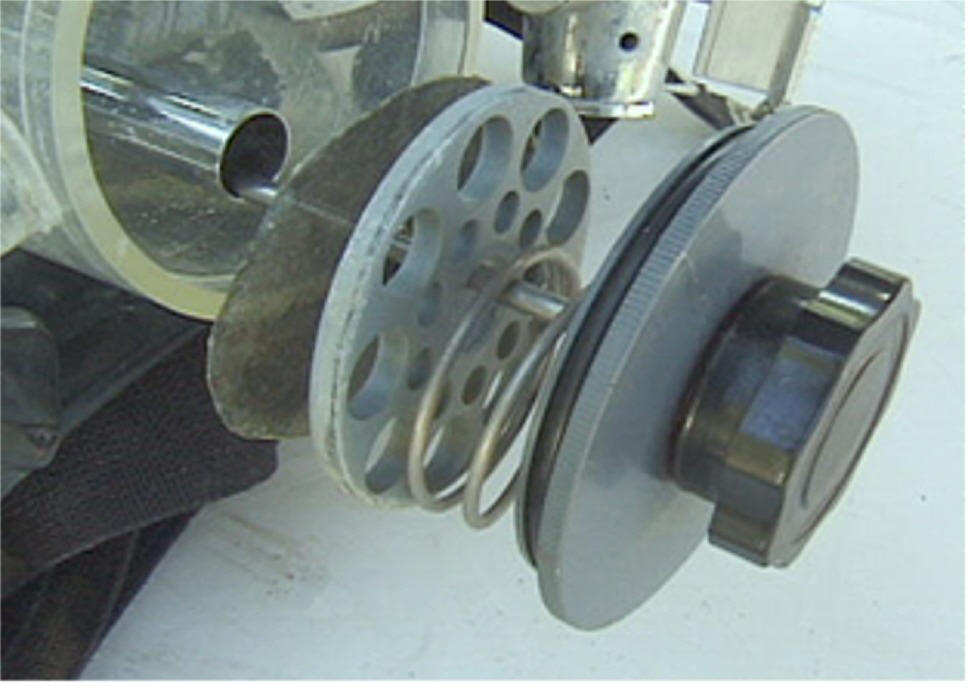
The absorbent canister
portion of the cylinder was a 12" section toward the bottom defined
by two 1/4" thick acrylic or PVC internal bulkheads perforated with
an array of holes. Plastic screen was used to keep the absorbent
from falling through the holes. The top bulkhead was fixed in
place. The bottom one was free to move but held in place against
the absorbent column by a large spring. This served to keep the
absorbent compacted without channelling despite any minor settling
of the granules after filling the canister.
We used Barylyme as an
absorbent. This is a National Cylinder Gas trade name for Barium
Hydroxide. It was widely used in hospitals and came in hermetically
sealed one quart cartons of the type used for milk. The Electrolung
canister held two cartons which would be sufficient for six hours of
moderate activity. We changed them after four hours. Barylyme came
with a colour indicator, pink when fresh, blue when expired. It is
less caustic than soda lime and worked well for us.
As described earlier
gas was drawn from the counterlung to the space at the bottom of the
canister down a central 1" ID tube leading from the inlet hose
attachment down to the bottom end of the canister section. From
there it passed back up through the absorbent into the
sensor/solenoid chamber and on via the inhale hose to the
mouthpiece.
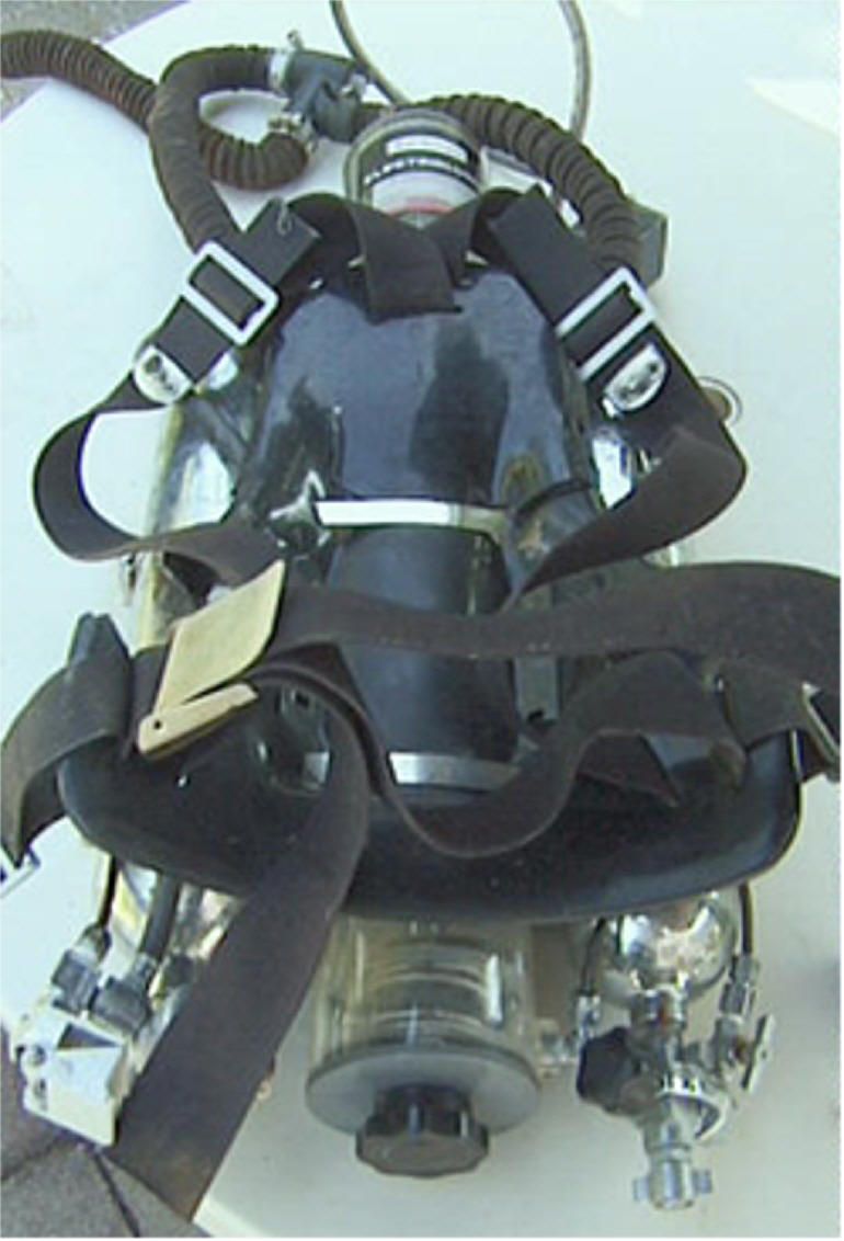
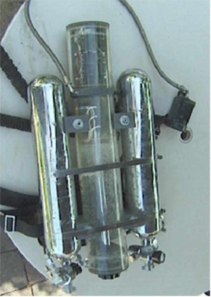
The gas supply
cylinders were mounted on either side of the absorbent
canister/electronics cylinder using spacer blocks conforming to the
curvature of the respective cylinders. The three cylinders were
secured rigidly in place by two large SS hose clamps. One was
adequate for the purpose so there was backup in the event of one
breaking. The spacer blocks also served as attachment points for
the harness which was a U.S. Divers one of the type widely used
before BC’s took over this function. There was a wide vinyl strap
for each shoulder plus a waist strap. The overall configuration of
the Electrolung backpack was similar in many respects to that of the
small triple tank OC rigs favoured by the French at that time. It
rode well on the back and was quite comfortable. All up weight of
the Electrolung was about 30 pounds.
Some people expressed
concern about the use of acrylic fearing the possibility of
breakage. This is one of those things which is more apparent than
real. In this case it is protected on one face by the wearers body,
on either side by steel gas cylinders and at top and bottom by thick
PVC ends. The only real exposure to any possible impact was the
curved surface of a 4 1/2' OD 1/4 thick cylinder which would be
extremely hard to break. We did look at using polycarbonate (Lexan)
which is literally bullet proof but found it crazed and crumbled
into small pieces when exposed to hydroxides. It would of course be
easy to make the whole thing of PVC but I feel the advantage in
being able to see condensation, water, and the condition of your
absorbent more than outweighs the non-problem of smashing heavily
into things while going backwards. Beckman offered a fibreglass
fairing for those who might be concerned with this but of course
some then bought it because they liked the way it looked and others
did so because they felt that if it was offered they probably should
get the complete set up.
A final aside for
homebuilders. The Electrolung was really a homebuilt which became a
commercial product. It was built entirely with a drill press,
lathe, and jigsaw; plus a bench grinder for shaping and sharpening
lathe tools as the only power tools. For anyone attempting to build
any kind of underwater equipment a metal lathe is really a must.
With one you can easily make all kinds of cylindrical housings,
O-ring sealed fittings, ports and closures, and any kind of threaded
fitting you might need. A small lathe with a five or six inch
swing over the bed will enable you to make housings and ports up to
10-12" in diameter. Good quality Chinese made lathes suitable for
this kind of work are now available for about U.S. $ 1500. For
another few hundred dollars you can also get a milling attachment as
well which is a useful addition.
Teaching yourself how
to use it is not hard. Good text books which cover this kind of
machine tool work are readily available and easy to follow.
The Electrolung patent
is online at
http://www.patents.ibm.com/details?patent_number=3727626
The online material is
a summary but you can order the full patent there. It contains much
more detail including various drawings.
VI. Final (Reflections and speculations)
Development of the
Electrolung came about through the chance meeting of John Kanwisher
and I aboard Ed Link's diving research vessel in the Bahamas in
early 1968. Ed was trying out his new diver lock-out submarine Deep
Diver and had invited along several researchers with relevant
interests. I was there to do some deep biological collecting and
John was there to do heart rate/respiration measurements on divers
using some new acoustical telemetry equipment he had developed.

Lock-out dives from
Deep Diver were done using hose fed OC Kirby Morgan helmets. Gas
for this purpose and to pressurise the lock-out chamber was supplied
from a large high pressure sphere carried by the sub. The large
amount of gas required for a single dive severely limited the number
of dives which could be made and involved substantial cost and
logistic considerations. The need for more efficient utilisation of
gas was clearly apparent.
It turned out that John
and I had both been considering the feasibility of a mixed gas CCRB
using electronic sensors to control PPO2. We both knew in general
terms what was needed but John wasn't a diver or a machinist and I
didn't know that much about electronics. However, I had been diving
for 15 years and had built a wide range of underwater equipment and
John, in addition to being a physiologist, had invented the first
polariographic oxygen sensor and held a dual appointment at Woods
Hole Oceanographic Institute and MIT where he lectured on electronic
instrument design.
When we returned to our
homes John started putting together the sensors and control circuit
and I started getting together the hardware and machining all of the
necessary bits. Six weeks later we both had our respective parts
together. John sent me the board and sensors, I installed them and
it worked. The overall configuration and design was basically as
described but there were, of course numerous details to clean up.
The electronics for example were wire connected on a breadboard and
the solenoid valve I had hand made and actuated with a solenoid
scavenged from a battery operated coo-coo clock.
Although the prototype
was put together quite quickly it was far from a "first thing which
comes to mind" effort. Quite a few years experience and thought had
led up to it so that when actual construction was began we both knew
pretty clearly what needed to be done and how to do it. Later at
Beckman I had the opportunity of working with a whole group of
specialists on improving the same device. The outcome was some
tidying up of details
but no fundamental
improvement. The biggest problem was to prevent the creation of
problems which didn't previously exist but could be introduced
through changes made by specialists who were unaware of consequences
outside of the narrow area of their expertise. The experience gave
me a real appreciation of both the power and the limitations of
specialist expertise and the importance of systems analysis in
co-ordinating and integrating the input of specialists.
Although development of
the Electrolung was interesting, even exciting, in itself it was
just an interesting incident in a bigger, far more interesting and
significant picture. Like most historical events, I suppose, what
was happening didn't appear to the participants at the time so
remarkable as it later does in the broader perspective of hindsight.
The larger perspective on what is taking place right now tends to
be somewhat obscured by the ordinary events of living. Except for
rare instances whatever we are doing, however interesting and
exciting it may be, tends to still feel like life, not like history
in the making.
In retrospect however,
I have come to realise that from the mid 1950 through the mid 70's
something really remarkable was taking place in diving. During that
period diving grew from the obsession of a small group of generally
impecunious young people mostly in FL, CA, France, and Italy to a
global industry catering to well-to-do hobbyists. Remote tropical
islands all over the world began to sprout airports and dive
operations and diving
became strongly
oriented to travel to exotic locations. Though all this was in
itself remarkable something truly unique was at the real heart of
what was happening.
For the first time in
history humans could freely enter, explore and personally experience
the oldest, richest, most beautiful and exotic communities in
nature, tropical coral reefs. Coral reefs are truly remarkable
places. Nowhere else can one experience such an abundance and
diversity of life. Nowhere else is it so colourful, exotic and so
easily experienced at close range.
Diving on a reef is
like a trip in a time machine to a time before humans existed and
nature ruled in primeval pristine abundance. Fossils of many reef
creatures from as much as 60 million years ago are essentially the
same as those on reefs now. In fact some Pacific reefs have existed
as reefs for that period of time.
For a biologist, being
among the first to dive on reefs was an extraordinary experience.
In a way it was a bit like landing on another planet. On nearly
every dive you were going where no human had ever been before. The
discovery of phenomena of life and strange and beautiful creatures
whose existence we never even suspected was an everyday occurrence.
At the time this kind of experience was so commonplace, tropic seas
so vast and remote, and so few people were doing it, that it began
to seem as if this was just the way things were and this kind of
experience would continue on indefinitely.
Already however, this
era has become history. Although there are vast amounts still to be
discovered about the details and inner workings of reefs, still
undiscovered species are getting harder and harder to find and
remote locations are becoming less and less remote. The experience
of being among the first to explore the richest realm of nature has
come and gone, not to be repeated.
On reefs, one niche
still remains. Actually it is a really big one. The zone below 200
feet, down to the deepest limits of what you might call part of the
reef community at about 600 feet, is still largely unexplored.
Although it is not so rich in life as the shallower regions it is
still rich in life and is an area about which we know very little.
As far as I am aware
the only person on the planet regularly exploring this zone is Rich
Pyle. What he is doing is really exceptional and he is doing it
essentially on his own. While discussion on the Rebreather List is
largely restricted to the technology and physiology as an end in
itself what Rich is doing goes well beyond this. As well as making
more deep free dives than anyone ever has before he is coming back
with knowledge and specimens from every dive. What he is doing is a
permanent contribution to knowledge which will stand long after any
of today's diving records are broken and
forgotten. I have never
met him personally and am commenting only out of recognition of
something exceptional.
Over the past 25 or
thirty years advances in diving technology have been almost
entirely small and incremental. The only real exception I can
think of is the development of dive computers. It appears we are up
against the realities of human physiology. With every increase in
depth and bottom time the cost, complexity , effort, and risk
increases exponentially while the return of useful achievement
remains more or less linearly related to bottom time.
The future it seems
lies in other directions, especially robotics. Here the advances
have been impressive and future development promises to become even
more so. Already we are at a point where more and more functions
previously requiring a diver can be effectively carried out by
ROV’s . It is not hard to foresee that in a few years most of what
we do at great effort and risk by diving can and will be done by
nerds at consoles. In fact, right now in the Gulf of Mexico Shell
and BP are drilling in 5000 to 6000 FSW and all work at the
wellhead is done by ROV'S.
If you find this kind
of scenario uncomfortable, don’t let it worry you. Long term
prediction, no matter how well reasoned and seemingly inescapable,
has a way of almost always being wrong. So much so that I have
often wondered if beneath the facade of Newtonian certainty of our
universe , somewhere in the iffy probabilistic realm of quantum
mechanics, there is not a relationship which dictates that the very
act of prediction sets in motion forces which generate a different
outcome. So if you don’t agree with my prediction, the good news is
that I may well have voided it by predicting it.
Fortunately, the real
outcome is usually even more interesting than any of the
predictions.
Walter Starck
|