|
 |
|

|
| |
| Philippe Combis sent me information about
there Oxy'Pic project. A joint venture project from France! The project is
still in progress. If you are interested to joint them please contact
Philippe! |
|
OXY' PIC, the big project.
Author: Philippe Combis
Edited: J.W. Bech
April 2006
|
| |
| UPDATE june 2006 |
| UPDATE september
2007 |
| UPDATE august /
september 2006 |
| |
 |
| |
 |
| |
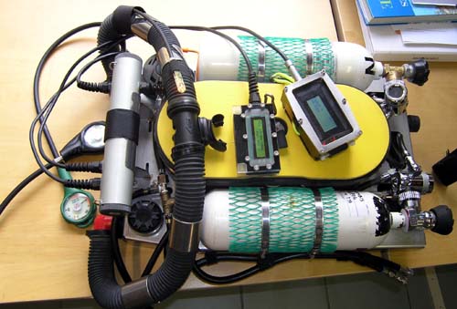
- Most of the analogue oxygen controllers are well
designed, easy to build and reliable, but they have 2 disadvantages:
- They usually have to be
manually calibrated.
-
- They usually are not equipped
with alarm functions.
-
- (alarms have a negative aspect too; they tend to
increase the vigilance of the diver..)
- This project has been made possible thanks to
communication on the Internet!
It is the result of sharing an experiment, competences and
friendships. Without the Internet it would never have become such a
success!
- Thanks to all sharing knowledge and information!
-
- The shared idea was to build a programmable
oxygen controller with following characteristics:
-
- Simple and innovating
-
- Compact ( you will see that that was a hard
thing to realise)
-
- Build with basic tools in a garage
-
- Simplified Calibration without the need to open
the rebreather
-
- Fitted with alarm, monitor, and a vibrating
warning device
-
- Large LCD screen
-
- Design with batteries in external container.
-
-
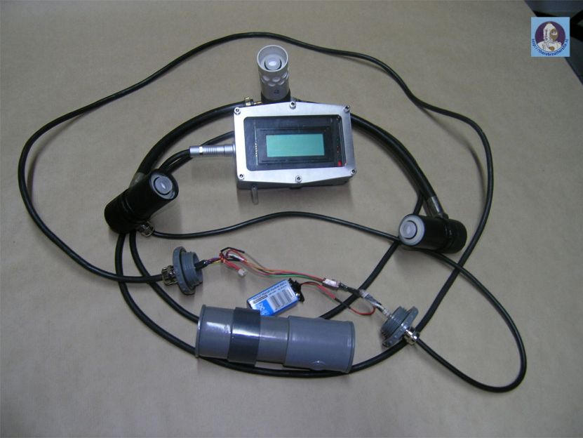
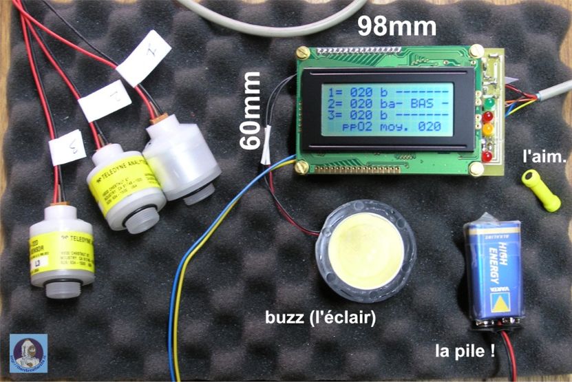
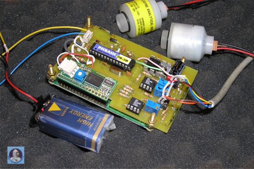
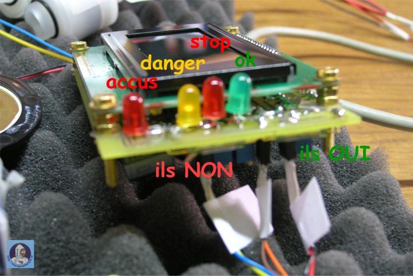
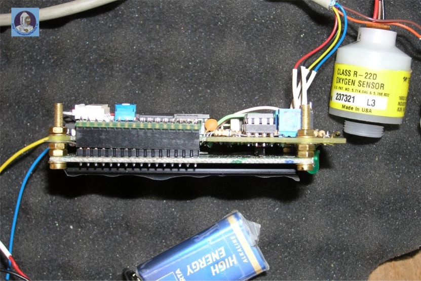
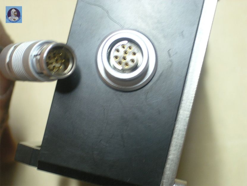
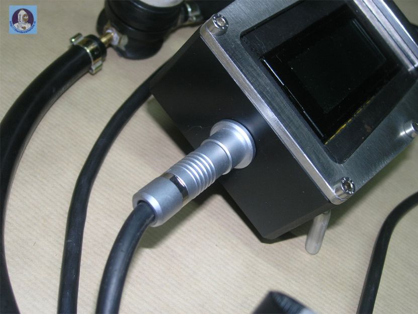
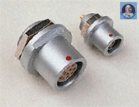
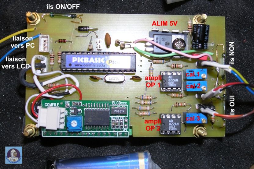
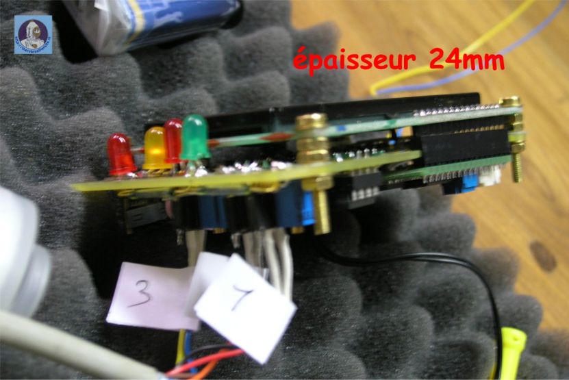
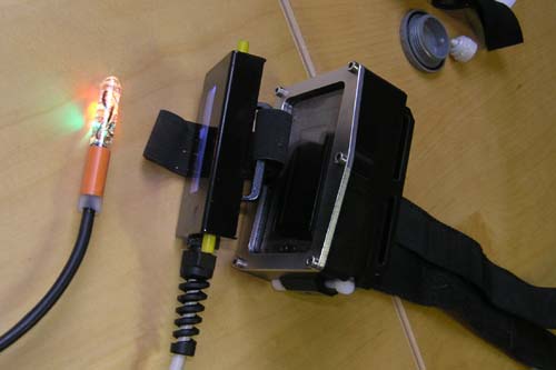
- Electronics:
Since I am not an electronics specialist I use a component that is easy
to program (directly on the PC) and using a simple interface called :
the PICBASIC from Comfile Technology™.
http://www.comfile.co.kr/english2/pb2000.html
This component has converters, analogical/numerical 10 bits, necessary
to the measurement of the PPO2 on the 3 cells, the entries for switches
and exits which makes it possible to control the led's, a buzzer, and a
vibrator.
For this project you will need:
- - 1 pc 5
volt power supply
- - 3 pc
amplifiers OP.
- - 1 pc
Pic integrated circuit.
- - 1 pc
buzzer
- - 3 pc
led’s
- - 1 pc
alarm vibrator.
-
|
 |
| |
 |
| |
 |
| |
 |
| |
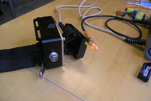
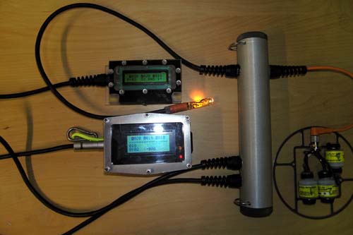
- The principle is very simple;
- 1 The cells are having an output of 10 mV in air
- Since this voltage is very low it is necessary to
amplify it with an amplifier like the model OP.
2 This voltage is added to a programmable PIC which transforms the
voltage into digital and one
displays the result on a display.
-
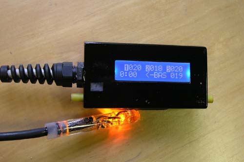
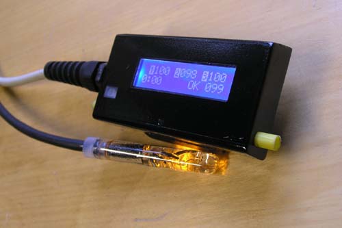
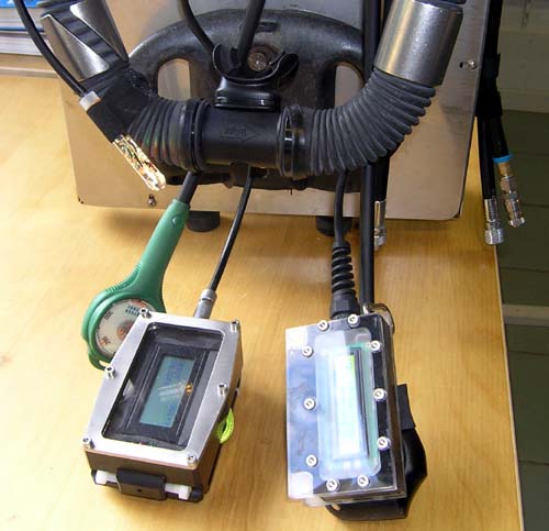
- Software:
The PICBASIC is programmed in BASIC.
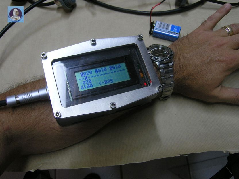
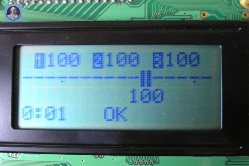
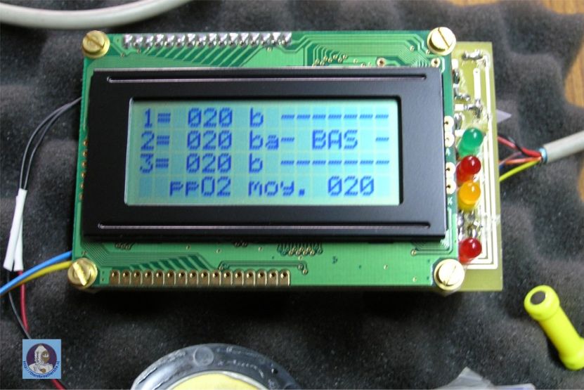
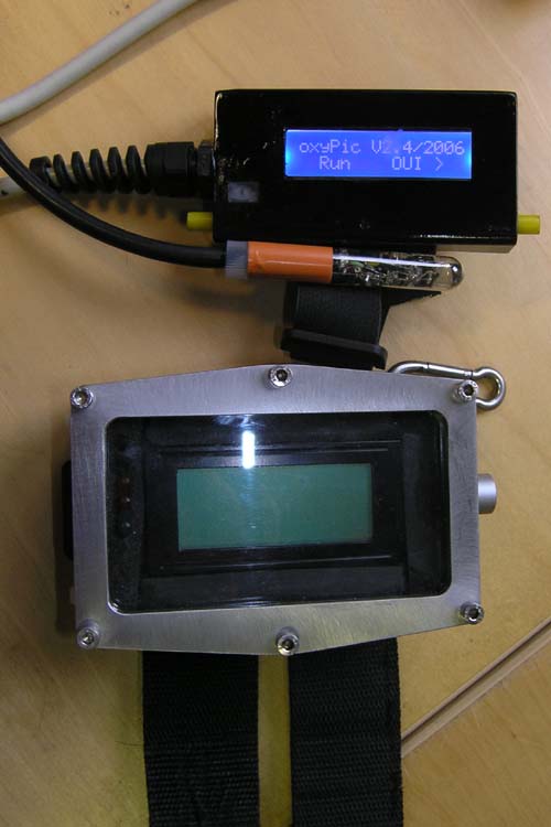
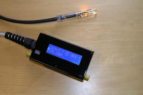
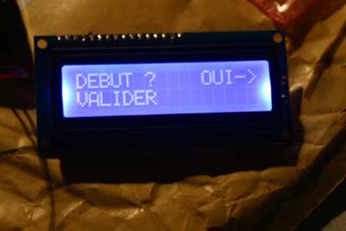
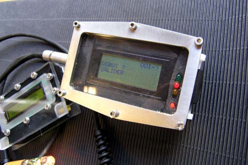
- Display, interface:
I have chosen a digital display showing four times sixteen lines.
Beware, this is very important since the lines decide how big the
housing will be.
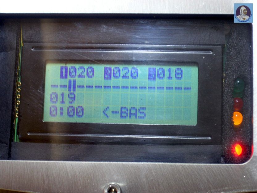
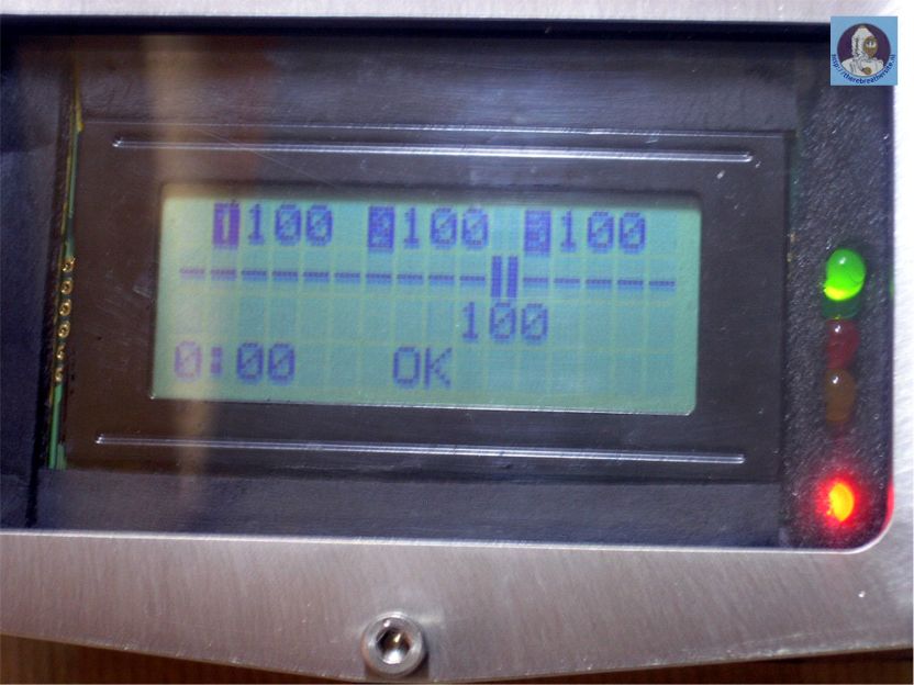
- first line: showing the pO2 of the 3 cells.
second and third line: a bar graph which indicates the average pO2.
fourth line: operating time (with a beep all 3minutes) and a message
(low, high, ok or what you want.)
|
| |
 |
| |
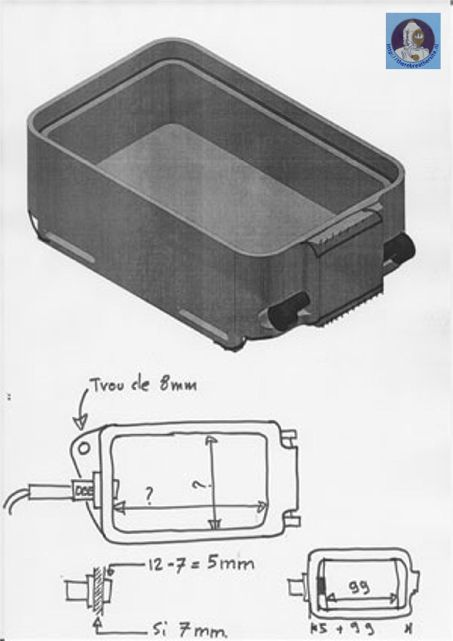
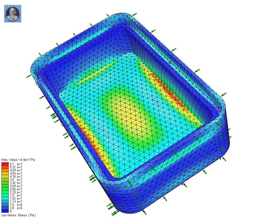
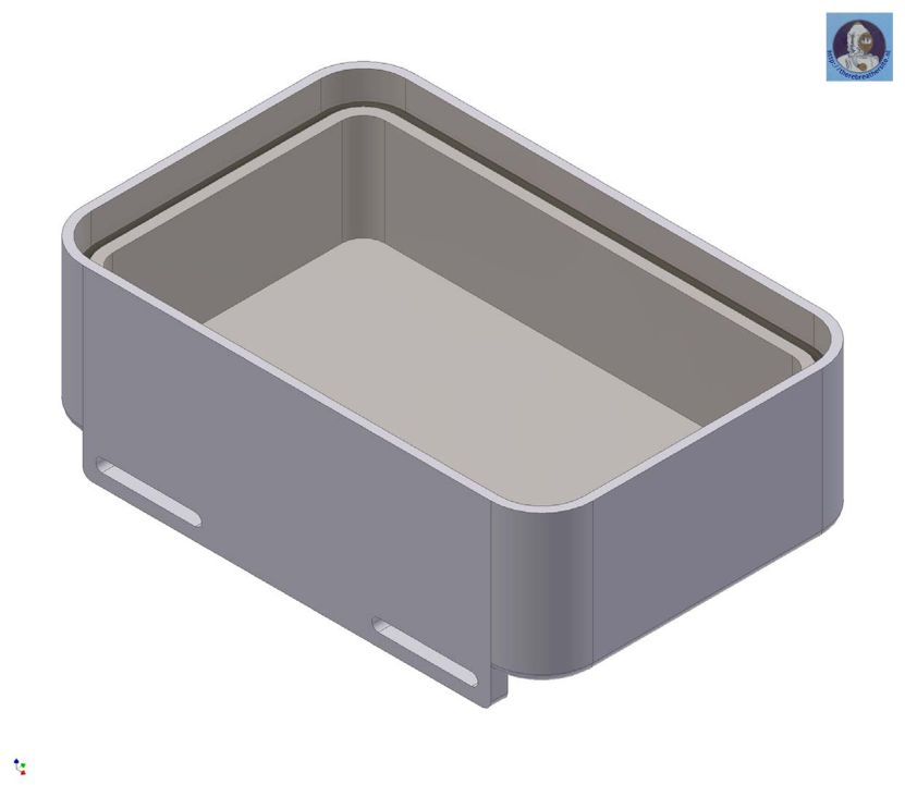
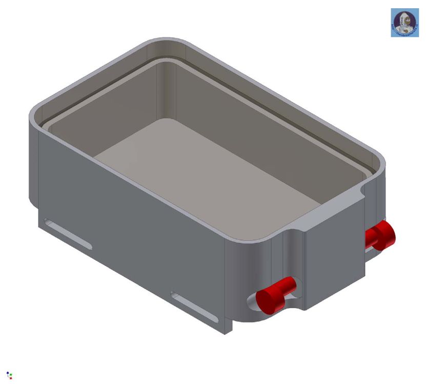
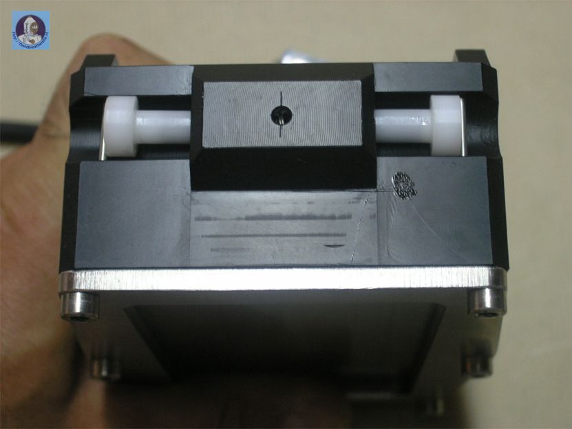
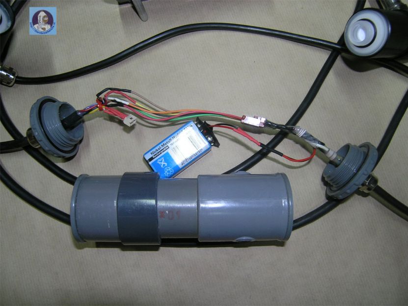
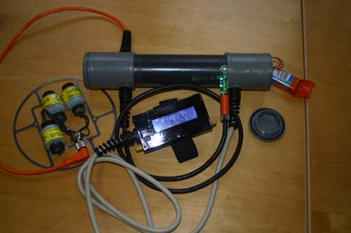
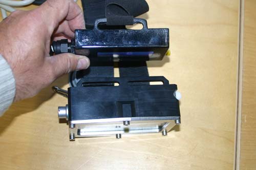
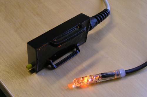
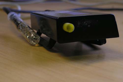
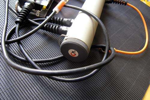
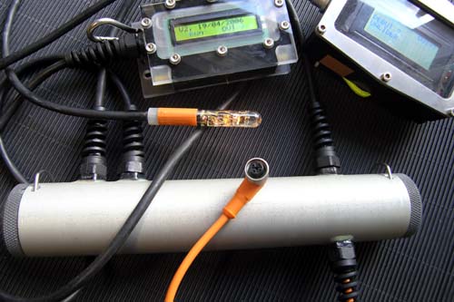
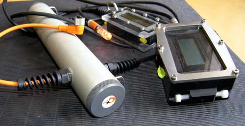
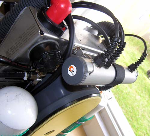
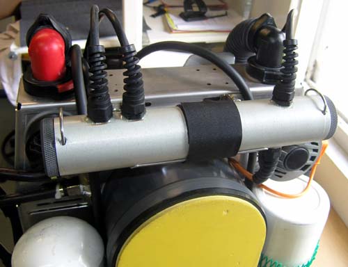
- The case: the most complicated part of the
project.
At the start of the project I had thought of building an epoxy case
(moulding). Unfortunately I did not succeed in making a functional
model. After this I decided it had to be made by CNC routing, but
unfortunately I do not own such a machine! Bernard M. living in
Swiss brought the solution and proposed to made the housing for me.
I gave him the dimensions of the housing and the position of the
magnetic contacts. In the design process we defined a maximum diving
depth of 80m for the housing.
We then performed data-processing simulations and used constrain
techniques to define the minimum thickness of the walls in POM.....
that gave us the external dimensions of the housing. These design
aspects took us 6 months, but the results where exceptional!
Now we have quality made in Swiss thanks to Bernard!
|
| |
 |
| |
 |
| |
 |
| |
 |
| |
 |
| |
 |
| |
 |
| |
 |
| |
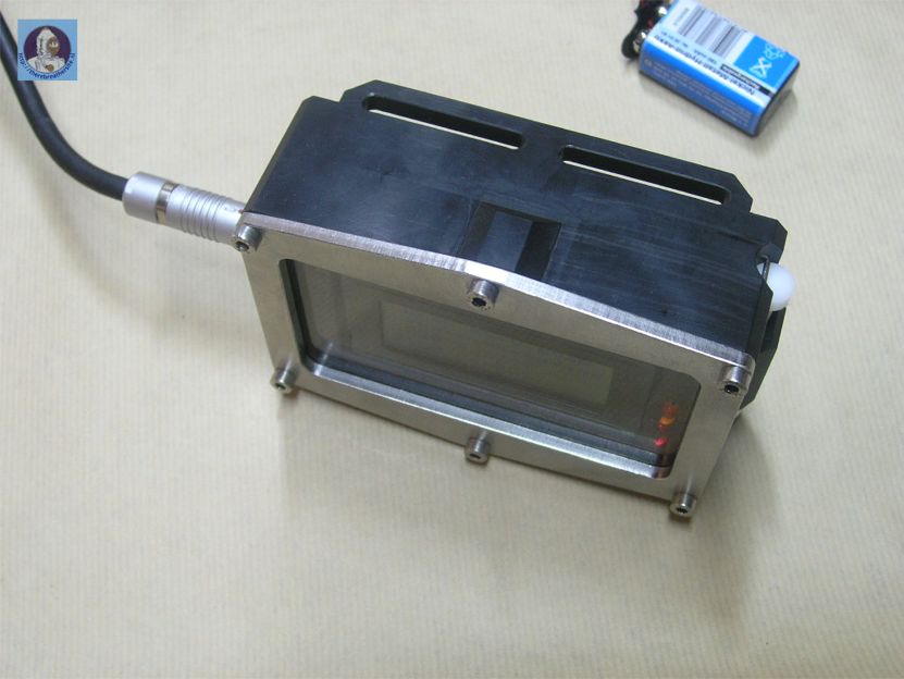
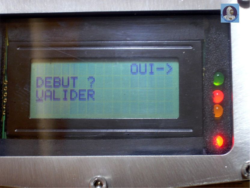
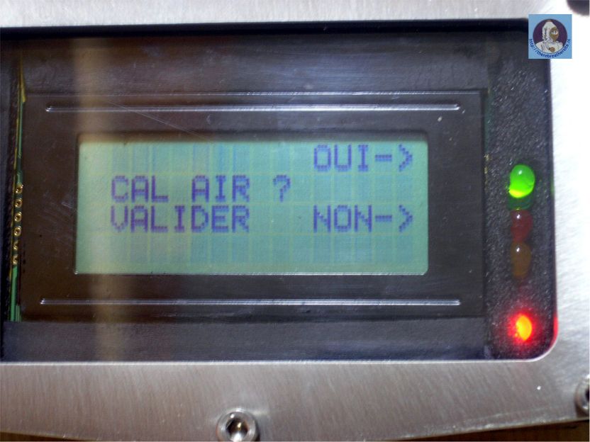
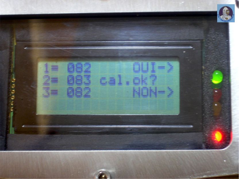
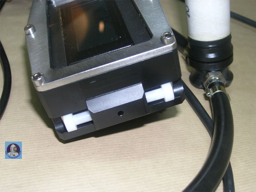
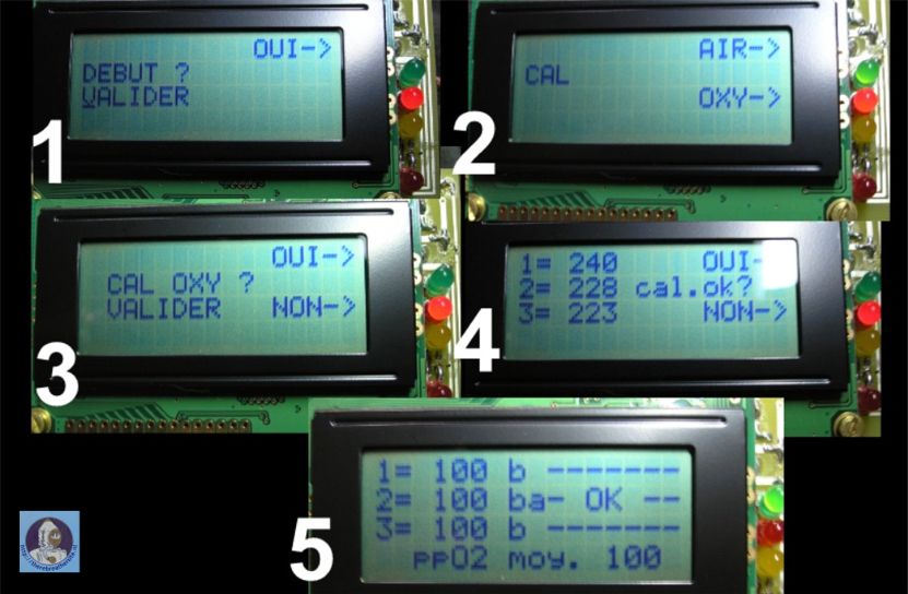
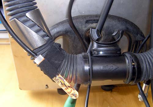
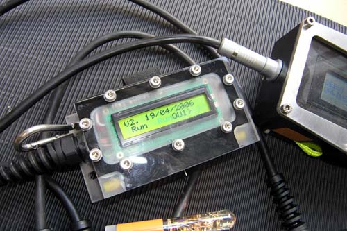
- Operation:
1) starting: remove the magnet hold by elastic cord! It is not beautiful
but it is efficient!
2) a message appears asking to confirm the start of the calibration.
3) then the user decides if oxygen or air is used for the calibration.
4) the choice has to be confirmed.
5) calibration starts.
6) posting the results of the measurement. The handset asks to confirm
the measured values.- 7) acceptance of measurement and switch to dive
modus.
-
- After this point it is not possible to stop the
unit to get into dive modus unless you use the external magnet to switch
the handset off.
|
| |
 |
| |
 |
| |
 |
| |
 |
| |
- Reliability:
- The unit is in a test phase.
The alarmvibrator is a very nice and functional warning system.
Led’s are hard to see.
Autonomy: no the problem.
- Test results: to be processed
- Further development:
-
- Realization of an analogical oxygen controller
- Realization of a HUD.
Realization of a version ECCR.
Realization of a more compact version.....
-
- Thanks for your attention; Philippe Combis.
-
- WWW:
http://archicom.chez.tiscali.fr//indexida.html
mail:
philippe_combis@(no-spam)yahoo.fr
|
 |
| |
 |
| |
 |
| |
 |
| |
 |
| |
 |
| |
 |
| |
 |
| |
| Philippe, thanks for contributing to my
website! |
| |
|
Update 2006 |
| |
|
 |
| |
|
 |
| |
|
 |
| |
|
 |
| |
|
 |
| |
|
 |
|
|
|
 |
| |
|
 |
| |
|
 |
| |
|
 |
| |
|
 |
| |
|
 |
|
|
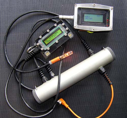
Update august/september 2006 |
| |
 |
| 1 |
 |
| 2 |
 |
| 3 |
 |
| 4 |
 |
| 5 |
 |
| 6 |
 |
| 7 |
 |
| 8 |
 |
| 9 |
 |
| 10 |
 |
| 11 |
|
 |
| 12 |
| |
| Philippe, thanks for the great pictures! |
| |
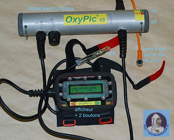
| Update September 2007 |
| |
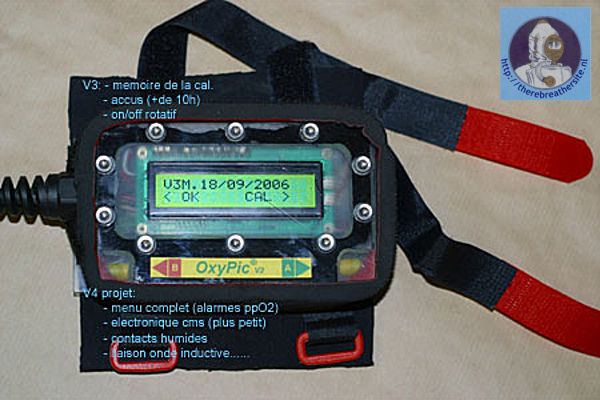
Philippe completely modified version
two into version three!
Please check his website for more details here:
http://archicom.chez-alice.fr/indexida.html |
| |
 |
| |
 |
|
|