 |
 |
|
|
Philippe sent me his excellent
story how he rebuild his Azimuth rebreather to a KISS style operated CCR.
Thank you Philippe for your contribution!
|
|
UPDATED 15 APRIL 2003
|
1. Overview of the rig
2. O2 First stage and cylinder
3.
Kiss valve
4. O2 feed
5. ADV on inhale counterlung
6. Hose re-arrangement and routing
7. PO2 monitoring
8) Azimuth Kiss style CCR schematic diagram
9. Part list
|
|
-
AZIMUTH CCR CONVERSION
-
1.
Overview of the rig
-
|
-
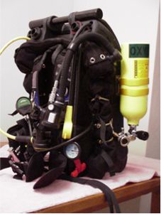
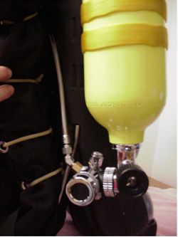
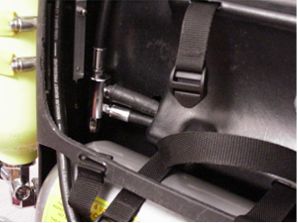
You can see the left side of the rig: O2 tank and Apeks DS4 first
stage, Air2 hooked up to bottom tank, bailout regulator 2nd
stage hooked up to top cylinder and the Oxygauge. I also use a VR3
with the external cell for PO2 monitoring (not presented on this
picture). The kiss valve is added next to the original dosage bloc
of the Azimuth. This configuration allows me to have 2 diluent
tanks both hooked up to OC for bail out. I changed the MR12
threads and tank valve of the top tank to DIN threads allowing me
to use the top tank as the O2 tank with the Apeks DS4 for shallow
dives or travel. But being in the USA, I found it difficult to get
an O2 fill in my Faber 4 litre steel cylinders which are not DOT
stamped and with a valve that does not feature a burst disc. So I
decided to go for the second set up as shown below.
|
|
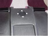
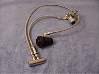
The Mares MR12 and the blue feed line are removed.
The input port on the dosage bloc is plugged. |
|
|
|
 |
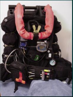
The picture on the left presents the other set-up, obviously more
streamline. This is the configuration I now dive most of the time. |
-
-
2.
O2 First stage and cylinder
-
-
|
-
|
-
- I simply used the Apeks
DS4 as O2 addition is to be done with
Gordon Smith’s Kiss
valve.
- The machined Delrin
plug is installed to block the ambient pressure chamber of the first
stage because the system requires a constant pressure regulator. An
overpressure relief valve is added here since the O2 add valve won’t
vent the excess pressure if the regulator fails but is more likely to
undergo “rapid-non-passive disassembly” (as per Gordon’s own words)
instead. Button-type high pressure gauge is presented here.
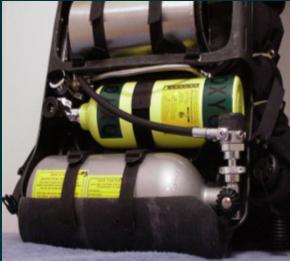
- I use a Catalina 13
cuft. The tank is attached with a quick release
bracket on the left side of the shell.
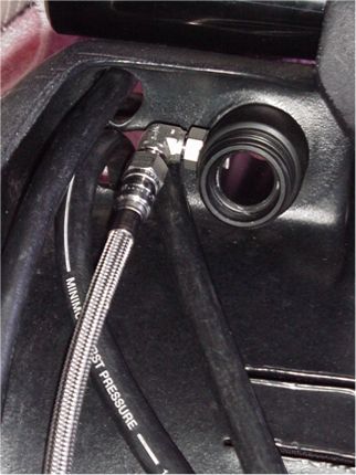
- The O2 feed line runs
from the DS4 on the left side to the O2 add valve on the right side
between the shell and the wing
|
-
-
-
3. Kiss valve
-
-
|
-
|
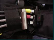
- The 02 addition line is
made using components sourced from
Gordon Smith
together with the Swagelok fittings as used in his KISS rebreather.
- It continuously injects
a small trickle of 02 into the loop at slightly less than the divers
metabolic use rate. A manual addition button is included for the diver
to replenish the loop with O2 and get back to the chosen PO2 set
point.
-
|
-
-
4. O2 feed
-
-
|
-
|
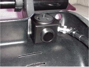
- I chose to feed 02 in
the exhale side of the loop as it gives time to the O2 flow, both
continuous and manual addition, to mix with the diluent.
- I used a Swagelok
fitting plugged into the fitting that was originally used on the
inhale side (I removed it from the inhale side as I added the ADV, see
below) to connect the hose to the inhale counterlung.
- The adjustable OPV is
removed as the exhale counterlung features a BC type spring loaded OPV
that would do its job in case of ascend on OC.
|
|
-
-
-
-
-
5. ADV on inhale
counterlung
-
-
|
-
|
-
Bob Howell’s ADV has
been fitted on the inhale counter-lung.
- The ADV is hooked up to
the Ray manifold that I added to the rig.
The fitting that was originally here is
now used to feed O2 on the exhale side (see above).
|
-
-
6. Hose re-arrangement
and routing
-
-
|
-
|
- I used the
manifold that is
fitted on the Dräger Ray to rearrange my hoses.
- BCD / AIR2, dry suit
inflator and ADV are hooked up here.
-
|
-
-
7. PO2 monitoring
-
-

|
-
|
- I added one
P-ports on each side
of the inhale counterlung to monitor the PO2 with an Oxygauge (right
side of picture) and the
VR3
computer (opposite side of the counterlung, left on the picture).
|
-
-
8) Azimuth Kiss style
CCR schematic diagram
|
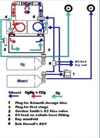
(Diagram adapted from OMG’s original diagram)
|
This is
the schematic diagram of the rig with the on-board O2 cylinder as
shown on the photograph above.
The
picture below shows the rig, ready to dive:
 |
-
9. Part list
-
-
- Kiss O2 feed line
-
-
-
-
-
|
-
-
Apeks first stage DS4
- O2 add valve
- Apeks first stage environmental plug
- Adapter 1st stage LP port to Swagelok fittings
- Hoses and fittings
-
|
-
- Dive shop
-
Gordon Smith
- Gordon Smith
- Gordon Smith
- Swagelok
-
|
-
- LP hose re-arrangement
-
|
-
- Ray manifold (part #
T53072)
-
|
-
- Watersafety.net
-
|
-
- O2 tank release bracket
-
|
-
- Aqua explorers Bracket
-
|
-
-
Aqua explorers
-
|
-
- PO2 monitoring
-
|
-
- P-ports (part #
T51193 + T51609)
|
-
- Watersafety.net
-
|
-
-
-
-
|
WARNING! REBREATHERS CAN AND DO KILL YOU.
The material presented here is for information only. It
is not a construction plan for doing this yourself.
IF YOU ATTEMPT TO MAKE MODIFICATIONS TO YOUR SYSTEM, YOU
DO SO AT YOUR OWN RISK.
I take no responsibility for your abilities, construction
skills, material selections or your judgment of your own diving skills.
|
|
|
|
|
|