 |
|||||||||||||||||||||||||
|
|
|||||||||||||||||||||||||
| This page is dedicated to the Steam Machines SM1600 rebreather. The relative rare rebreather won't be often seen in Europe. Stefan Besier did it again! He offered me this document and shows his great skill in commenting on a machine! And what a machine! It is a fantastic unit with legendary predecessors. Although almost new (build 2001) only two dozens of these beauties where made. The page is graphically heavy but worth the waiting. Shas en Peter, thanks again. A special pat on the back for Stefan! He will be out there at DEMA checking out the latest on recycling machines.... | |||||||||||||||||||||||||
|
THE STEAM MACHINES SM 1600 CCR Author: Stefan Besier Published with permission of Steam Machines Incorporated Published in http://www.therebreathersite.nl October 2004
After the recent photo shoot of
a pair of Innerspace Corporation
Porpoise Pac Ones I had the opportunity to shoot a
Steam Machines SM1600. Just in
time before the company's move to Tennessee, one of Steam Machines customers
offered his unit for sale through the company. This is usually the case with
used SM1600 and Prism Topaz, and I got some time with the rig before it was
shipped to its new owner. |
|||||||||||||||||||||||||
 |
|||||||||||||||||||||||||
|
Whereas the
PP-1
was a derivate of the CCR1000, commercially marketed in the 70s, the
SM1600 is an updated version of the MK15.5 that was sold to civilians. Known
as the MK15MOD1 in the military, it is more commonly know as the MK15.5, a
fitting designation as it is a combination of the MK15's parts and layout
with the MK16's center section design.
|
|||||||||||||||||||||||||
Since this document is rather large I made a small speed menu for jumping
through the document:
|
|||||||||||||||||||||||||
 |
|||||||||||||||||||||||||
 |
|||||||||||||||||||||||||
| BACK TO THE INDEX | |||||||||||||||||||||||||
|
|
|||||||||||||||||||||||||
 |
|||||||||||||||||||||||||
|
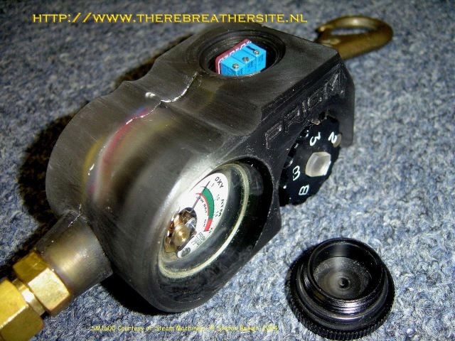
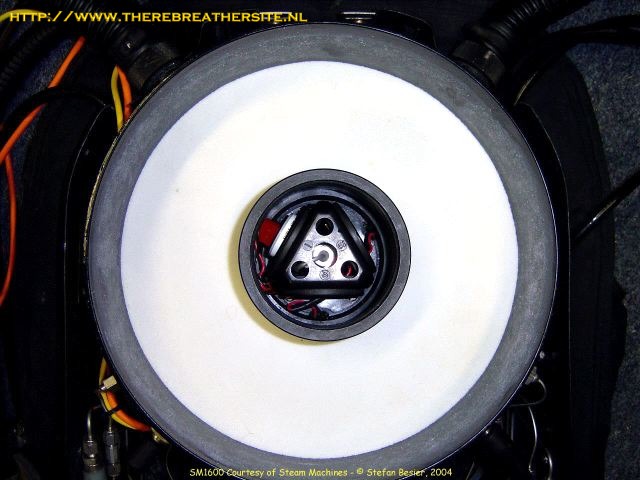
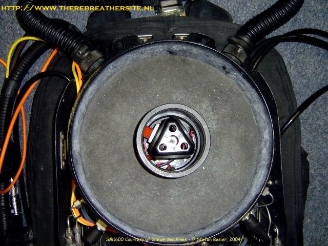
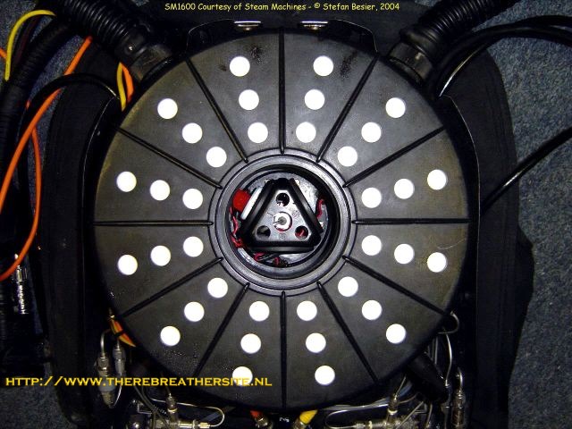
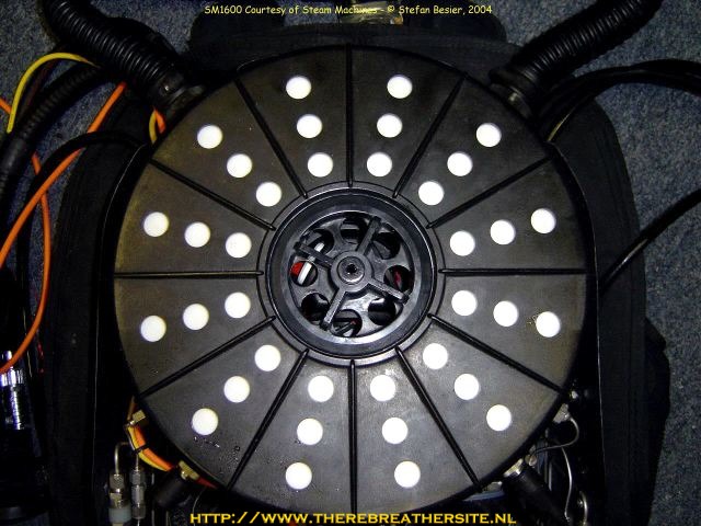
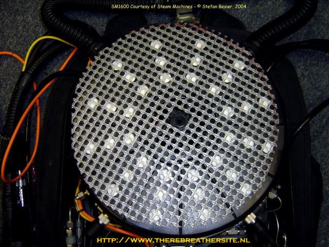
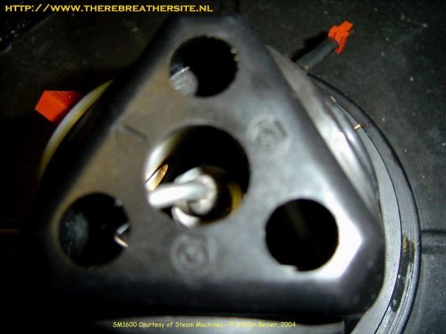
The 'trademark' of all MK series rebreathers and their derivatives, the circular protrusion that houses the center section. |
|||||||||||||||||||||||||
 |
|||||||||||||||||||||||||
 |
|||||||||||||||||||||||||
|
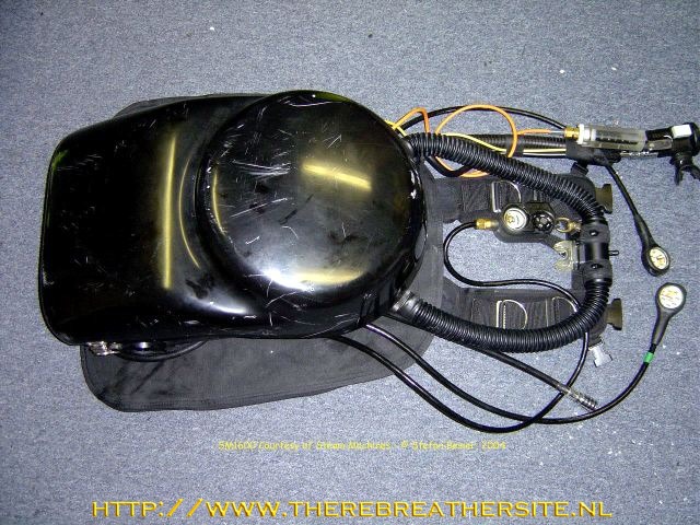
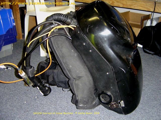
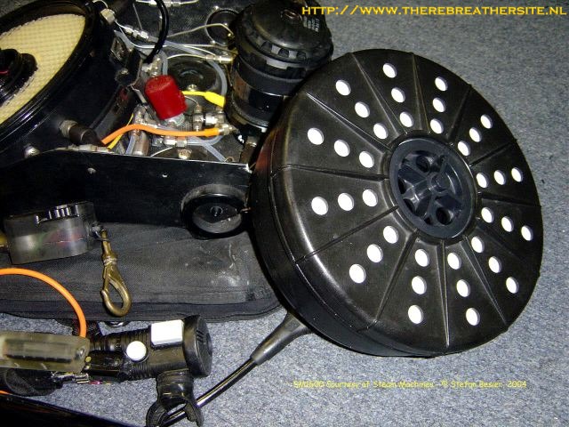
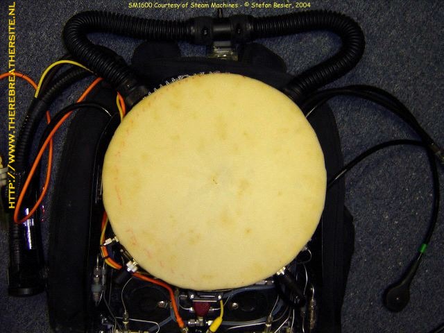
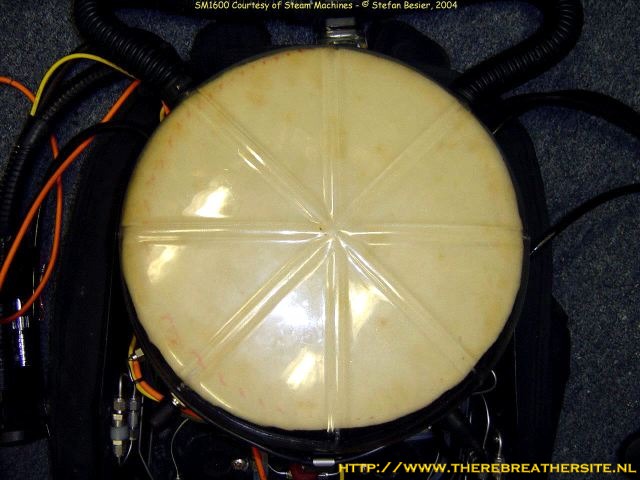
These top and side views of the unit show the increased depth over the MK15, brought forth by the larger center section and accentuated by the fully inflated 45lbs bladder. |
|||||||||||||||||||||||||
 |
|||||||||||||||||||||||||
|
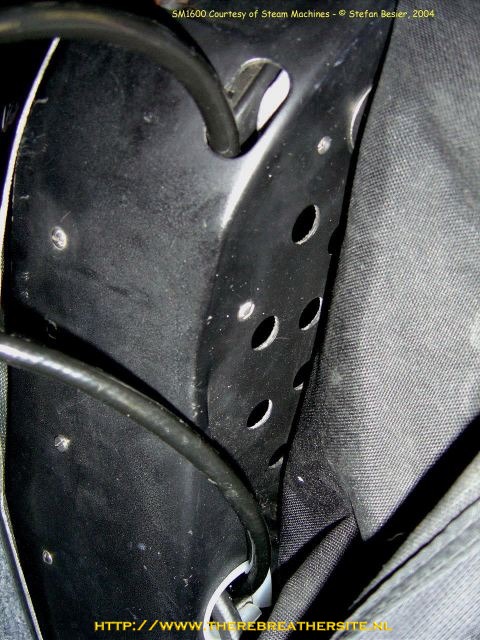
Here is a look at the side of the case facing the diver. Multiple holes provide ambient pressure for the counter lung, which sits well protected on the inside, while the larger ones route various cables and hoses out. Overall a very tidy and streamlined design. |
|||||||||||||||||||||||||
 |
|||||||||||||||||||||||||
| THE CONTROLS | |||||||||||||||||||||||||
|
|
|||||||||||||||||||||||||
 |
|||||||||||||||||||||||||
|
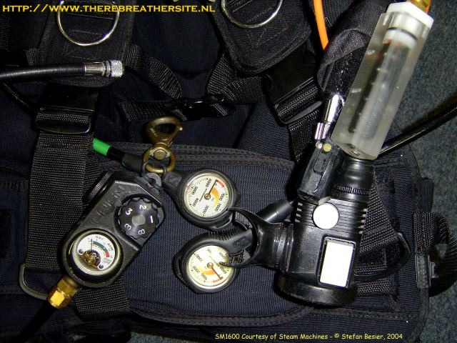
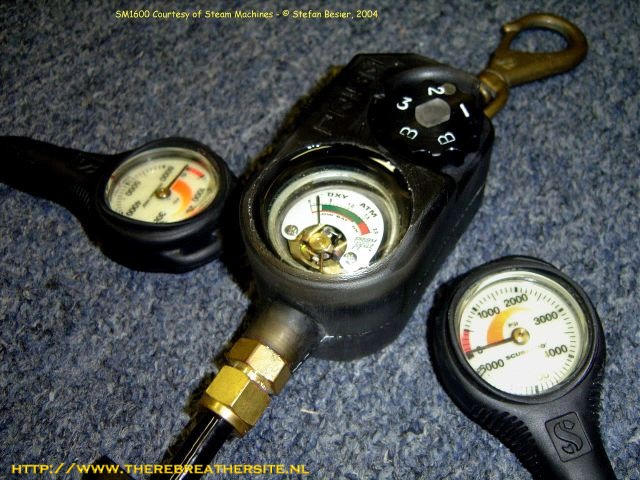
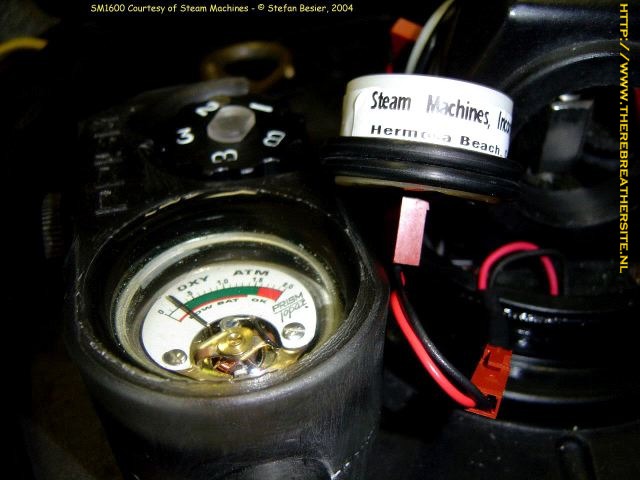
The three analog gauges side by side. The contents gauges are Scubapro Mini gauges, while the secondary fitted on this unit is a Prism secondary rather than the standard Carleton gauge. |
|||||||||||||||||||||||||
 |
|||||||||||||||||||||||||
|
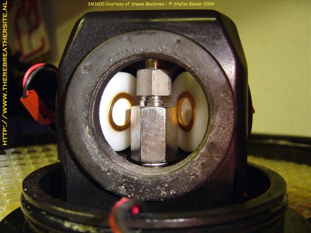
A close-up of the secondary shows the calibration pod for the three sensors. Adjusting the corresponding screws will adjust the needle across the scale until it reads 1.0 in 100% oxygen. The 'B' settings on the display will show the battery status while the electronics are switched on. A second 'B' position was added in lieu of the Prism's 'S'etpoint as the SM1600 does not display the setpoint on the secondary. |
|||||||||||||||||||||||||
 |
|||||||||||||||||||||||||
|
|
|||||||||||||||||||||||||
 |
|||||||||||||||||||||||||
|
On the opposite side of the exhalation port. These ports have a larger diameter as the ports on the MK15, thus improving the work of breathing. The two knobby bits on either side prevent a foam pad from covering the port. As the MK series design has only one counterlung, which is on the inhalation side of the centersection, the exhaled gas flows right into the scrubber cannister.
|
|||||||||||||||||||||||||
 |
|||||||||||||||||||||||||
|
|
|||||||||||||||||||||||||
 |
|||||||||||||||||||||||||
|
This cannister is an advancement in comparison with the MK15's in several ways: Rather than being made of metal it is moulded from glass reinforced ABS to give better insulation, the center section it is placed in as well. This increases the absorbent's scrubbing duration. The cross-sectional area of the inlet and outlet of the cannister is greater, again aiding to reduce the WOB. Finally, the scrubber is much easier to pack and pack correctly due to the removable lid rather than the 15's small fill port. The same of course goes for post-dive cleaning, a major improvement in convenience. The only drawback is the increased size of the cannister and center section mentioned before. |
|||||||||||||||||||||||||
 |
|||||||||||||||||||||||||
|
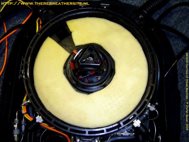
The center section of
the SM1600. The exhaust port is on the upper left, the gas flow of the unit
is counter-clockwise. The moisture absorbent foam pad is in place to trap
water that may enter through the port. In the center the sensor housing, and
around the outside edge slots. Both route gas into the counter lung once it
has passed through the scrubber. On the bottom of the picture some of the plumbing can be seen. It is here that the center section of the SM1600/MK15.5 and the Mk16's differ, as they have different pipework and gas addition valves. While basically the same design, they cannot be interchanged (without modification). |
|||||||||||||||||||||||||
 |
|||||||||||||||||||||||||
|
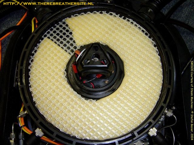
The plastic support screen insures that there is space between the absorbent pad and the permeable membrane so gas can enter the cannister. The cannister is than placed into the center section. |
|||||||||||||||||||||||||
 |
|||||||||||||||||||||||||
| This is the inside of the cannister with the white membrane through which the gas enters. | |||||||||||||||||||||||||
 |
|||||||||||||||||||||||||
|
On top of the membrane comes another absorbent pad. This one serves a dual purpose, not only absorbing moisture, but also shock. It is a reliable low tech approach instead of a spring mounted retainer frequently used. The absorbent is filled at this point of the cannister assembly (though usually while outside the center section to prevent dust from entering the inhalation side of the loop and sensor array!). |
|||||||||||||||||||||||||
 |
|||||||||||||||||||||||||
| The lid has been placed on the cannister holding the absorbent. | |||||||||||||||||||||||||
 |
|||||||||||||||||||||||||
| The locking screw in the center of the cannister keeps the lid down tight, while still allowing some of the exhaled gas to pass past the sensors. | |||||||||||||||||||||||||
 |
|||||||||||||||||||||||||
 |
|||||||||||||||||||||||||
|
The same setup from the inlet side of the cannister is repeated on the outlet side: A plastic support screen separates the cannister form the moisture absorbant foam pad. |
|||||||||||||||||||||||||
 |
|||||||||||||||||||||||||
|
Finally the lexan dome is installed onto the center section, sealing it and leaving only the inhalation and exhalation ports open. The clear dome allows a visible check of moisture/water inside the center section without breaking the seal. The raised, star shaped ridges allow condensation moisture to accumulate and drain into the inhalation bag. The diaphragm that makes up the counterlung sits on the opposite side of the centersection and is fitted with a baseplate and an OPV to prevent damage due to improper venting. With some training, the OPC allows to expell some water from the loop. As the center section was bolted into the case and my time with the unit limited, I didn't get a chance to photograph that entire side of the SM1600. The design of the center section is the hallmark of the MK series, and an exercise in brilliant rebreather design. This is even more appearant when considering the age of the original design (1960s) and the problems some recent designs have with condensation across the sensor faces.
|
|||||||||||||||||||||||||
 |
|||||||||||||||||||||||||
 |
|||||||||||||||||||||||||
|
Once the gas has passed through the scrubber and is moist and warm it hits the lexan dome and its flow gets split. It is here and then that most of the condensation occurs, with the resulting moisture trapped in the foam pad. Some of the gas flows though the slots in the outer rim of the center section into the counterlung. The rest is routed to the inhalation lung through the hole in the center where the sensors are placed. The combination of condensation along the dome and foam pad, reducing the amount of gas entering the sensor space and placing the sensors in the warmest possible area enclosed by the scrubber successfully prevents condensation problems on the sensors. |
|||||||||||||||||||||||||
 |
|||||||||||||||||||||||||
| BACK TO THE INDEX | |||||||||||||||||||||||||
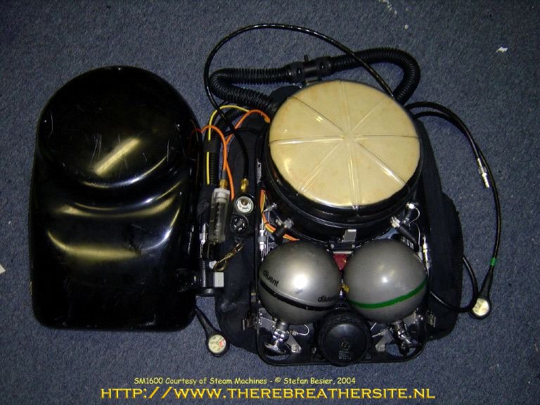
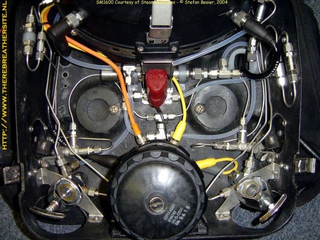
|
Intimidating to see for the first time, the layout is actually quite simple. The diluent tank and all its related valves, piping and filter are on the left. All of the O2 is on the right. The electronically controlled gas addition components are top on centerline, while the electronics are on the bottom centerline. On the very top is the clamp that secures the lexan dome. There is another one on the opposite side, and both are secured with a large O-ring encompassing the entire center section. |
|||||||||||||||||||||||||
 |
|||||||||||||||||||||||||
|
Diluent enters the pipework through the yoke style first stage, which takes it to the 60 mc filter. From there it goes to a T-section that supplies both manual and automatic diluent addition. |
|||||||||||||||||||||||||
 |
|||||||||||||||||||||||||
|
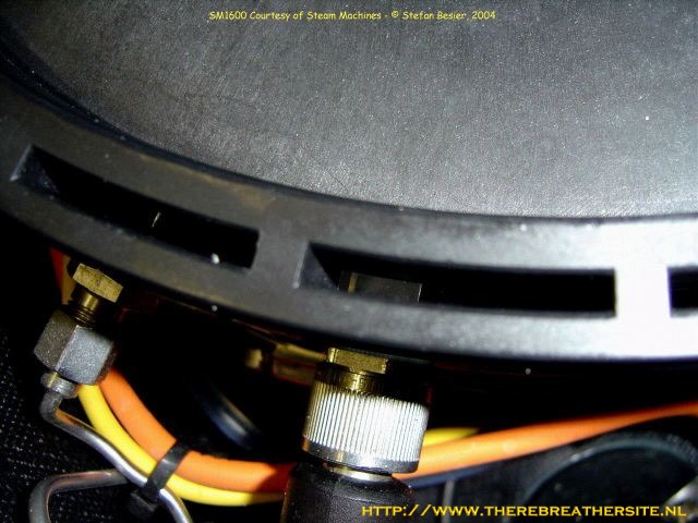
On the left side of the case is the easy to locate yet well protected manual diluent addition button. |
|||||||||||||||||||||||||
 |
|||||||||||||||||||||||||
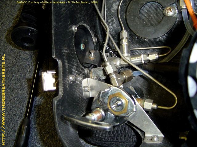
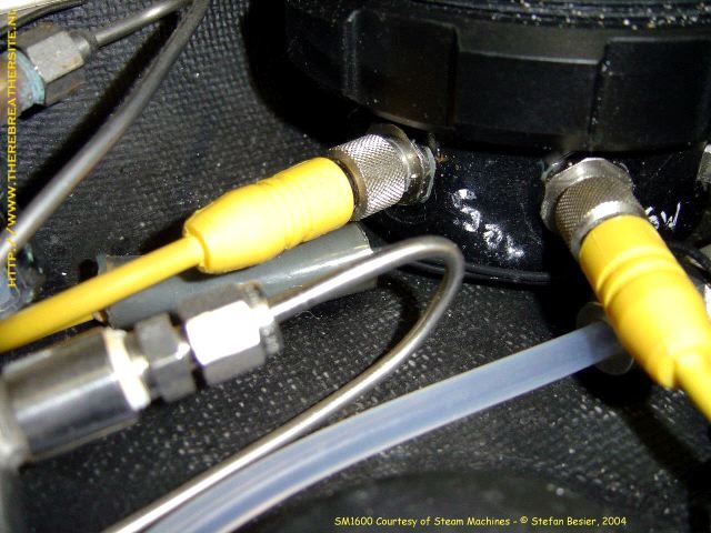
|
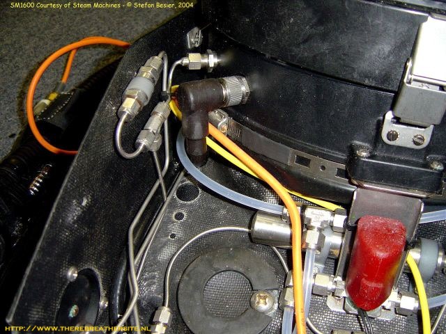
The automatic gas
addition is piped into the center section by the upper connection. Both
automatic and manual addition is directly into the counterlung to provide a
fresh, known gas when needed. The bigger lower plug is a Bendix connector
that feeds the current generated by the three sensors with the electronics
pod. The pipe work for the O2 supply mirrors the diluent side, the gas is routed through a filter and split by a T-section. Instead of feeding gas to an ADV, one end supplies the accumulator for electronic injection. The other routes the manual addition supply, first to the valve and then into the center section. |
|||||||||||||||||||||||||
 |
|||||||||||||||||||||||||
|
The manual O2 addition button is in a similar position on the right side of the case, and, as on the left side, there is a latch that secures the lid. |
|||||||||||||||||||||||||
 |
|||||||||||||||||||||||||
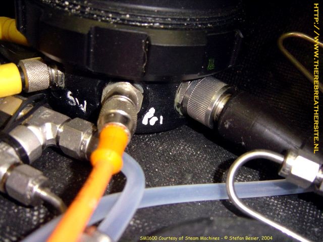
|
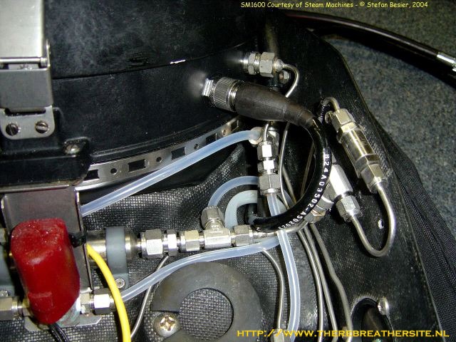
Here a close-up of the
O2 filter and centersection connections. Also clearly visible in this shot
is the mix of metal piping and clear, flexible, though not 'soft' tubing.
This differs from MK15 and MK16 as well as other versions of the MK15.5.
Steam Machines used the transparent tubing to enable the diver to visually
check the gas supply for contamination or moisture. |
|||||||||||||||||||||||||
 |
|||||||||||||||||||||||||
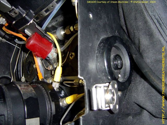
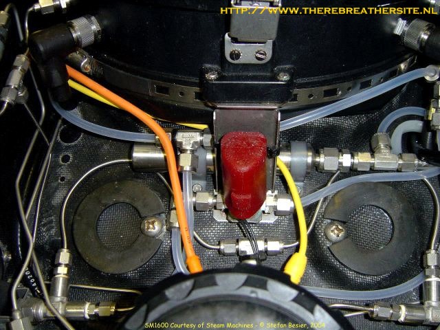
|
The red gizmo is the cover of the solenoid. Using a solenoid valve to electronically control O2 addition is a commonality between the MK15 and 15.5 designs, whereas the MK16 uses a piezo-electronic valve. The metal container placed perpendicularly between the solenoid and the centersection is the accumulator. It assures that a measured amount of O2 (50cc at 1ata) is injected into the loop every time the solenoid opens. |
|||||||||||||||||||||||||
 |
|||||||||||||||||||||||||
|
|
|||||||||||||||||||||||||
 |
|||||||||||||||||||||||||
|
Steam Machines used its propriatory SMS202 sensors. One can be seen here
next to the analog secondary measuring the ambient air and reading .21 bar
pO2. Designed by Steam Machines for use in an UBA, and manufactured for
them, the SMS202 are high output sensors generating between 16mV and 22mV
during their useful life span. Which, like most other sensors' is one year.
The high output is needed to drive the analog needle gauge, basically a mV
meter with a pO2 scale on its face. It runs directly off the current
generated by the cell, without the need for a separate power supply or any
other connection to the electronics. That makes the analog secondary one of the most important safety features of the MK15, MK15.5 and theSM1600. It provides a separate and completely independent pO2 readout from the primary LED display that can be used even with the electronics switched off, battery dead or either flooded, damaged and otherwise malfunctioning. This works together with the power switch shown earlier. Like the electronics and displays it is completely potted, and, like the thumbwheel on the secondary, a magnetic reed switch. The power switch physically disconnects both battery leads, reliably cutting of the power supply from the electronics. A safety feature often underestimated as it prevents stray currents to cross the sensors in case of a short or like malfunction. Thus the reading of the secondary won't be fudged. This combination of independent, analog secondary and physical battery disconnect switch was used only on MK15s and MK15.5s with OEM electronics from Biomarine, Carleton and Steam Machines. Aftermarket electronics manufacturers use a different setup, as does the the MK16. |
|||||||||||||||||||||||||
 |
|||||||||||||||||||||||||
| THE ELECTRONICS | |||||||||||||||||||||||||
|
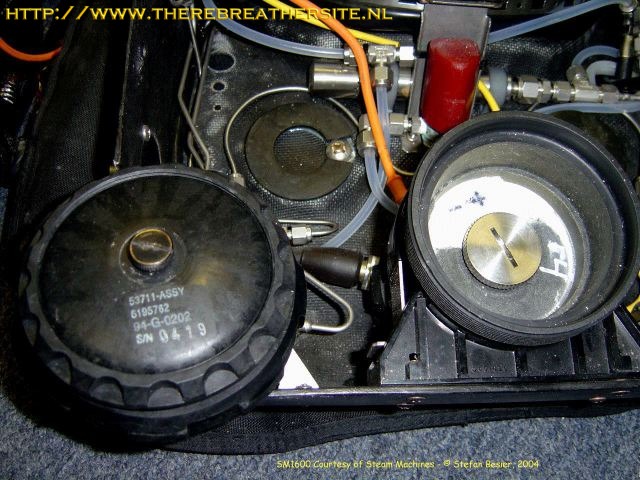
The only electronic devices in the loop are the sensors as requested by the Navy. All MK series CCRs have the electronic gas addition valve placed outside the loop to prevent sparks inside the potential high O2 environment. Same for the battery and electronics. The latter are housed in a separate pod, with the electronics placed in the bottom and the batteries in the top compartment. For normal diving operations only the top of the pod needs to accessed. In the picture the battery and battery cable are removed and the lid placed next to the pod. |
|||||||||||||||||||||||||
 |
|||||||||||||||||||||||||
| The battery lid has a pressure relieve valve (screw) on top, a jack ring and a threaded retainer. | |||||||||||||||||||||||||
 |
|||||||||||||||||||||||||
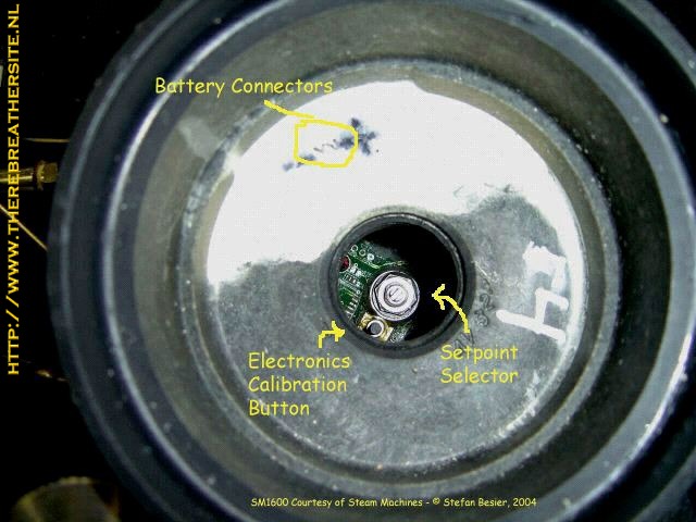
|
The
inside of the battery compartment with the potted battery connector pins and
the access port to the digital electronics. The port gives access to two
items used by the diver, the electronics calibration button and the setpoint
selector. After calibrating the secondary by adjusting the three small
screws, the primary is calibrated by gently pushing the calibration button.
Very simple procedure. Then the setpoint is selected. The available
setpoints, chosen before the dive, are 0.7, 1.0, 1.2, 1.3 and 1.4 bar. The
SM1600 is equipped with a depth sensor that switches the setpoint from the
0.7 bar shallow water setting to the selected setpoint at a depth between
15fsw and 18fsw (5msw and 6msw) on descent, and back to 0.7ata during
ascend. Forgetting to switch setpoints during the dive is impossible and the
danger of incurring the related deco obligation by accident eliminated. The use of digital Prism electronics are a major advancement over the older analog MK15 electronics. One of the important and different features of the the electronics in SM1600 and the Prism is cell validation. The performance of the cells is tracked and recorded by the electronics for comparison. The changing mV current generated by the cell and depending on ambient pressure and O2 content is compared to previously recorded values of the each cell as well as the other two cells. Response to changes in ambient pressure and/or O2 injection is tracked, and the condition of the cell validated. In the rare occurrence of two cells going bad, the electronics will know and notify the diver via the primary's LEDs accordingly. Whereas most other rebreather electronics would vote out the remaining good cell and use the two bad ones to maintain the setpoint, adding O2 into the loop and raising it to dangerous and possibly fatal levels, the two Steam Machines shut down the solenoid and signal the problem. As a single cell is not deemed safe to run a CCR electronically, the diver can monitor the remaining working cell on the secondary, validate the reading with occasional diluent loop flushes and fly the rig manually. |
|||||||||||||||||||||||||
 |
|||||||||||||||||||||||||
|
The
battery compartment, sized for the MK15's custom battery is O-ring sealed
from the electronics compartment with a metal lid. It dwarfs the small
standard 9V battery. The battery supplies power to the electronics, solenoid
and primary display, is easily available and lasts about 40 hours. |
|||||||||||||||||||||||||
 |
|||||||||||||||||||||||||
|
The
left cable sends power to the solenoid for electronically controlled O2
addition. |
|||||||||||||||||||||||||
 |
|||||||||||||||||||||||||
|
The thick Bendix connector and cable carry the pO2 feed from the sensors in the centersection. The orange cable next to it leads to the primary. |
|||||||||||||||||||||||||
 |
|||||||||||||||||||||||||
| THE DISPLAYS | |||||||||||||||||||||||||
|
The
primary display has 6 colored LED's placed in line. From left to right,
these signal the following information: |
|||||||||||||||||||||||||
 |
|||||||||||||||||||||||||
|
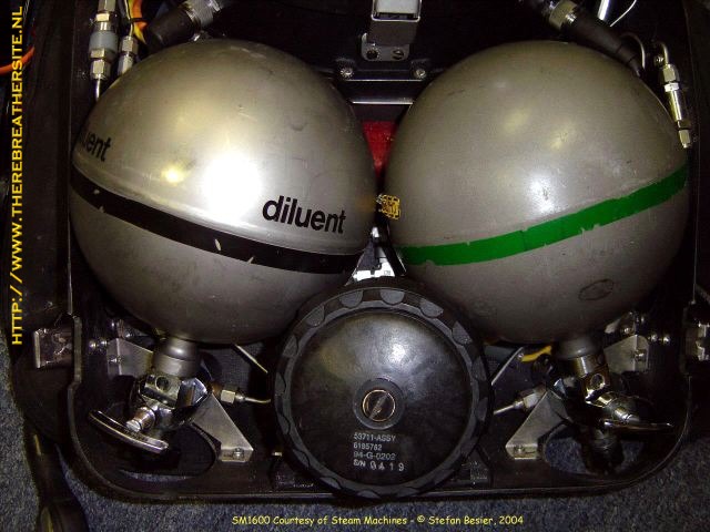
The final components of the SM1600 UBA, the flasks containing the gas. All SM1600 were delivered with Inconel® spheres made by Tavco in California. They are the same non-magnetic (inconel)flasks used in theMK15,5 and MK16, unlike the the earlier CCR1000 tanks made from steel. While they are light weight and the most efficient use of space, containing 21 cu.ft. of gas each, they need to be x-rayed instead of hydroed. Even getting the annual visual inspection and sticker can be daunting, and many dive shops refuse to fill them due to the lack of DOT certification. The spheres are equipped with pillar valves, the O2 valve has a smaller diameter than the diluent valve. |
|||||||||||||||||||||||||
 |
|||||||||||||||||||||||||
 |
|||||||||||||||||||||||||
|
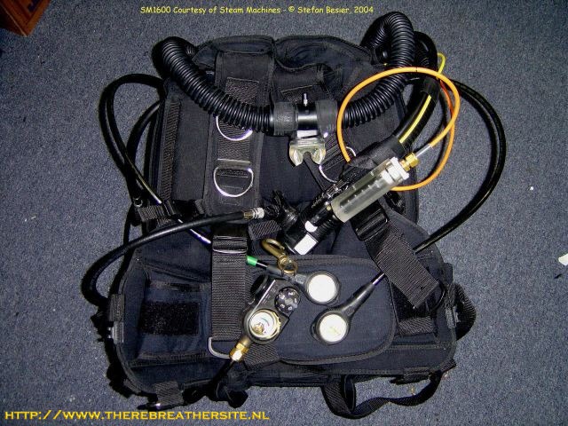
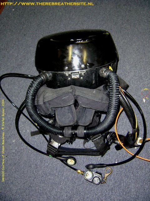
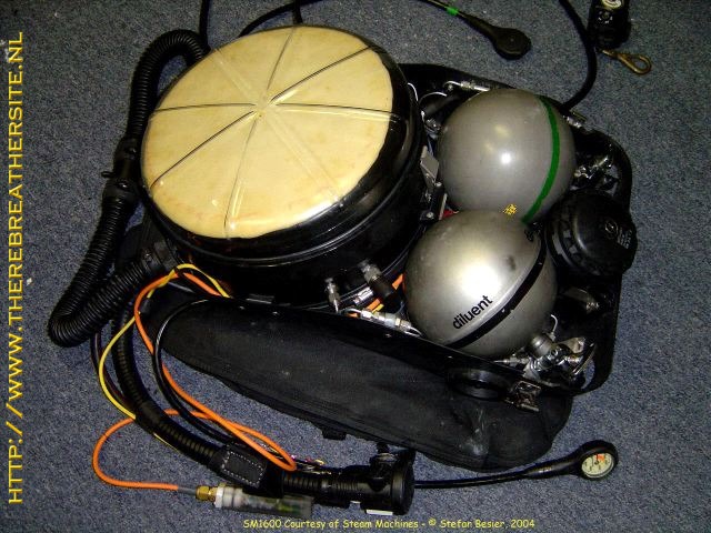
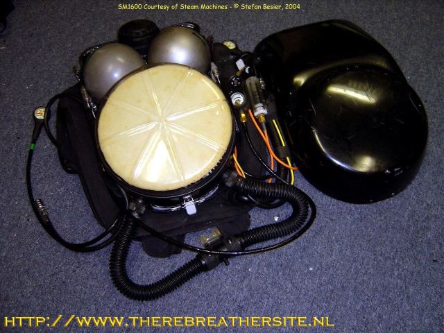
The completely assembled SM1600 shows the efficient use of space that makes the MK15.5 such clean package with all components except the displays well protected inside the case. |
|||||||||||||||||||||||||
| DOCUMENTATION | |||||||||||||||||||||||||
|
|
|||||||||||||||||||||||||
 |
|||||||||||||||||||||||||
 |
|||||||||||||||||||||||||
 |
|||||||||||||||||||||||||
|
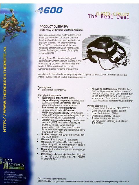
This was the original information sheet from Steam Machines.
It lists the general
features and specifications of the SM1600. The scrubber duration for the
MK16-shared scrubber, as tested by the Navy, was 284 minutes at 35˚F
(1.6˚C), 300 fsw (91.4msw) and 1.6lpm CO2/min ..... but to 1.0%
CO2 in the loop! That value has changed, today rebreathers are
tested and rated to 0.5% CO2. |
|||||||||||||||||||||||||
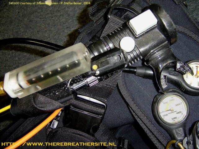
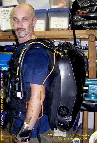 Stefan with SM1600 ;)) October 2004 |
|||||||||||||||||||||||||
|
After helping to move a large lathe from the 2nd floor to the trailer outside and about 2 1/2 hours of moving about a windowless room without air conditioning in the California summer heat, disassembling, arranging and shooting, the rig is back in one piece and modelled by the exhausted author. Thanks to Jan for taking the shot. |
|||||||||||||||||||||||||
 |
|||||||||||||||||||||||||
|
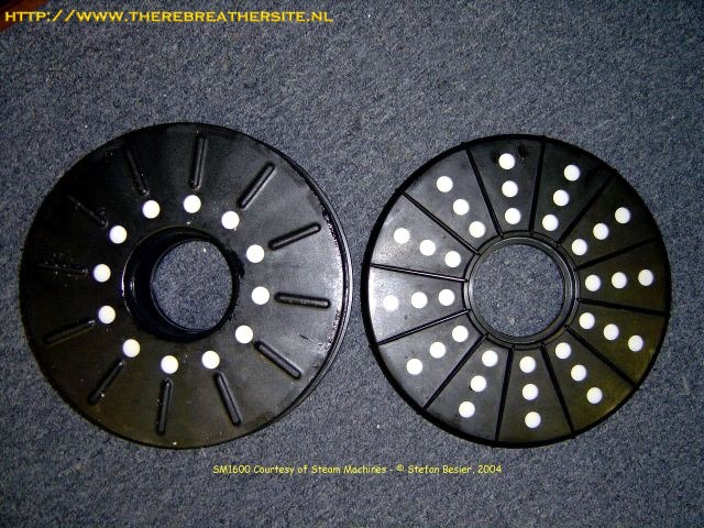
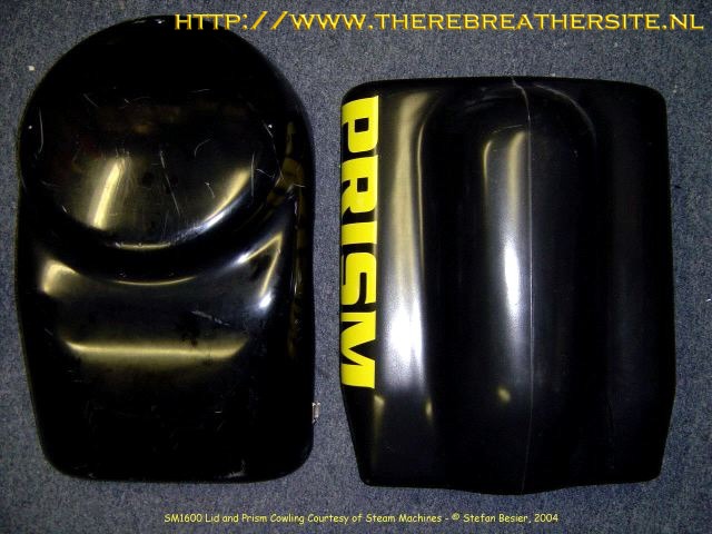
For size comparison, as well as a little teaser for an upcoming feature, a side-by-side picture of the SM1600's lid and the Prism's cowling. |
|||||||||||||||||||||||||
|
Finally, my thanks and appreciation to Janwillem Bech for hosting the article and supporting rebreather divers and interested parties worldwide with information. Stefan Besier USA2004 |
|||||||||||||||||||||||||
|
|||||||||||||||||||||||||