| New manual coming soon! The Sentinel only available in one model now! |
| Latest information about the Sentinel design concept available here by Kevin Gurr December 2010 (click text) |
| THIS PAGE IS GOING TO BE UPDATED IN DECEMBER 2010 WITH NEW INFORMATION! (06-12-2010) |
 |
 |
 |
 |
|
|
The energy expended by a diver to push gas around a rebreather is a
combination of three primary things.
1. The resistance to flow of all the bores within
the unit (houses, mouthpiece etc.). At the surface as a diver
breathes out and in again a breathing performance analyser will show
a rise and then fall in pressure throughout the breathing cycle.
This is known as the Pressure/Volume diagram or PV diagram. At the
surface it is a sideways ellipse about zero pressure, much like the
shape of your eye. The area within this ellipse is measured in
Joules/liter and is known as the Resistive Effort (RE) required to
push gas around the breathing circuit. At depth with increased gas
density this ellipse will fatten, increasing the Joules/liter. An
increase in breathing rate also increases the joules/liter. |
 |
|
If the counterlung you are breathing into is too small for a
standard breath, the two ends of the ellipse will turn up and down
respectively. Further degrading the 'breathing feel' and increasing
the peak to peak pressure felt by the diver. |
 |
|
A low RE is essential in any rebreather design as the effects of it
cannot be compensated for by the diver, it is purely a function of
the mechanics of the rebreather.
2. Once the unit is submerged, hydrostatic effect now plays a part. Depending on the test position (vertical or horizontal), the shape of the counterlungs (long/thin Vs doughnut etc.) and their position in the set will affect the angle of the ellipse. The ellipse, previously about zero, will tilt up to add a minimum and maximum peak pressure to the PV ellipse. These peak to peak pressures also affect 'breathing feel'. If the Counterlungs (CL ) are long and this and the unit is anywhere other than horizontal the PV will start to angle up considerably, again degrading the 'breathing feel'. |
 |
|
A CL of a safe minimum size (so as not to affect 1 above), shaped
around the centroid position of the divers lungs will produce lower
peak to peak pressures. Both this and the RE are tested at depth
with high ventilation rates, as again the diver can do nothing to
correct these issues in set design except breathe slower.
Hence the results from 1 and 2 are additive and go towards the total
'breathing feel' of the unit.
3. A final function is important and that is the Rotational Hydrostatic Effect ((HE). This simulates the diver moving into different positions. It is function of 1 and 2 above and the counterlung position (and shape) with reference to lung centroid in these varying positions. It is currently conducted with a fixed loop volume so that comparisons can be drawn. The rotation has the effect of moving the angled PV diagram up and down about the zero point (and in some cases modifying the angle) and in effect creating an offset (addition/subtraction) in peak pressure. |
 |
|
So for the total 'breathing feel' of a set, 1,2 and 3 are all added
together at this stage. Test 3 gives the only result where the diver
has the ability to compensate for the pressures seen at the
mouthpiece as they can vent or inject manually in the different
positions or change position, thus improving the 'feel' somewhat.
Units with overshoulder counterlungs generally have a lower HE. But
if counterlung volumes are excessive or are not constrained, the HE
results can be compromised significantly.
Backmounted counterlungs traditionally show high HE when the diver
is swimming on their back.
So given that the total breathing feel of a set is a function of all
three of the above, almost any CL concept can be made to generate a
good overall work of breathing. Overshoulder counterlungs
traditionally solve the HE problem quite well but designs often
compromise items 1 and 2 as a result, which remain un-adjustable by
the diver.
Over-shoulder CL's have their own issues such as 'harness clutter'
and large buoyancy shifts, which can in-turn affect the sets ability
to track PO2 setpoint accurately.
Absorbent Filters Traditionally we have been led to believe that axial designs are a low-duration performer and radial is high. This is not always the case. What can be said is that radial designs have a lower breathing resistance due to the bed length and are often less prone to packing errors due to the bed height versus the pack down % (at least in doughnut radials). |
 |
|
The Sentinel can use three different absorbent systems in the same
mechanics. Each can interface with our Canister Duration Meter (CDM)
which is a licensed United States Navy product we have rights to.
The CDM is a thermal system which predicts the 5mb CO2 point on a
duration curve.
Version 1 is a user-packed granular system. The absorbent canister
is located over the CDM and filled. Being a user-packed axial design
you are required to tap the sides of the canister and then refill it
to the top again (as per the instructions) before replacing the lid.
The CDM assembly is spring loaded into the canister base and the
base fitted back into the rebreathers’ centre section. This process
disengages the spring plate and forces the canister up into a seal
in the canister head. Both auto-aligning the filter and continuously
re-packing it during use.
Version 2 uses a pre-packed, disposable granular cartridge which is
'snow storm filled' to remove packing errors. It in turn fits onto
the CDM and locates in the same way.
Version 3 uses the polymer bonded Extend air cartridges which again
locate on the CDM in the same way. When using versions 2 and 3, an
additional sealing O ring at the base of the CDM comes into play and
like the top seal should be kept clean and greased.
The Extend air cartridges give several advantages over granules such as a lower breathing resistance and easier flood recovery. |
|
Counterlung
The unit comes as standard with one
back-mounted counterlung (CL). This CL is teed off of the inhale
side of the loop at the output of the canister head, hence the
inhale breathing hose is not actually connected to it, it is just
provides an expandable volume. In a head-down position water will
preferentially drain into the CL. When the diver goes head-up again,
water drains back to the canister base where the water/gas dump is
positioned.
The single back-mounted CL has several
advantages;
1. More protection
2. Less heat loss
3. Simpler flood recovery
4. Reduction of failure points
Mid 2008 a second option will be
available. The set will be available without its' hard case.
Cylinders will attach to the canister centre section as will a
harness/BCD support and a single, cordura covered CL will plug
into the existing CL position and be attached over the shoulders to
the harness.
This configuration will allow the diver to travel with a
small/lighter set.
Gas systems
The set has no high-pressure (HP) hoses.
It uses digital HP sensors fitted directly into the first stage. The
digital HP provides content and usage/leak alarms.
The set uses the same oxygen solenoid as
the Ouroboros. It is rated to over 15 bar as an interstage pressure.
The regulator first stages are Poseidon Extremes with a 12 bar
(approx.) over pressure valve (OPV), primarily to protect the
solenoid and low pressure (LP) piping.
The LP circuit does not use conventional
hoses. It uses super-flexible LP tubing with a woven
protective cover with a burst pressure of 200 bar. The tubing is
more resilient to UV and saltwater in long-term use than rubber. It
is also lighter and more flexible.
A Level 1 system does not have any
manual gas addition (bypass) valves. Levels 2 and 3 have gas
injection blocks mounted on the shoulders of the harness (one each
side). The block can manually inject gas into the loop. On a level 3
unit each block also has an isolating slider for the oxygen solenoid
and the automatic diluent valve (ADV) should they fail in an open
position.
A level 3 unit can also have an
off-board gas connector (Swagelok) fitted to each block. This system
is unique in that it not only allows off-board gas to be injected
manually but it also routes it through the automation (ADV,
solenoid). The diluent off-board is even available at the Bailout
Valve (BOV).
The BOV is integrated into the mouthpiece (which is neutral in-water). The second stage is a Poseidon Extreme. Rotating the switch selects open or closed circuit. |
|
With a level 1 system. A 'red' alarm on
the HUD will trigger a response to switch to open circuit and
ascend.
With level 2 and 3 systems. The BOV is
used as a 'sanity' breath system. This is especially useful in
hypercapnic incidents where there is a strong desire NOT to switch
off the set to an alternative bailout regulator. The 'sanity breath'
allows you to asses the situation and then take the correct action.
The BOV and breathing hoses are counterweighted to offset buoyancy.
The breathing hoses are fitted to the
canister head via a dual lock quick-release system, compromising a
quarter-turn and a push button. The hose ends are double radial
O-ring sealed. The complete mouthpiece and hose assembly can be
quickly removed for cleaning as can the CL.
The diluent LP circuit is fed from the
first stage through a multi-port manifold to allow connection of
BCD/suit feeds etc.
The HP sensors use a 'dynamic reserve'
system. On the diluent side, dependant on depth and an assumption of
open-circuit breathing rate, the reserve alarm will vary. Hence in
shallow water the alarm will trigger later compared to deep water,
still allowing a safe ascent to the surface.
Oxygen setpoint control is also dynamic.
The set can be put in 'auto-setpoint' mode (only levels 2 & 3 are
selectable, level 1 is auto only). Level 1’s maximum PO2 is set to
1.2 other levels are selectable up to 2 bar PO2.
Upon submersion the unit will slowly
increase the setpoint to the preset during the descent. Once at a
stable depth the diver can select the high setpoint themselves or
wait until the set automatically switches.
Upon ascent the set will remain at the
high setpoint until the safety or required decompression is complete
and then decrement towards the surface (reducing to 0.7) to avoid
unnecessary buoyancy shifts.
The loop over-pressure valve is located
in the canister base. It is also the water drain. It is unique in
that it can be set on the surface for a given pressure and then
irrespective of the position of the diver in the water, it will
always dump at approximately the same pressure.
The cylinders in a level 1 unit are a 3l
(diluent) and a 2l (oxygen). Level 2 & 3 sets come with dual 2l
cylinders. As the base foot of the case is extendable (or removable)
longer cylinders of a similar diameter can be fitted. As the 1st
stages are free to move, almost any style of cylinder valve can be
fitted. The standard valve supplied is an AP Diving cylinder valve.
Electronics
The unit comes with electronics similar
to the Ouroboros with a different human-computer interface (HCI).
There are two HUD's, one front and one rear. A Primary display and a Backup display (levels 2 & 3 only). There will be an option mid 2008 for an intelligent Backup display which will double as a data logger and dive computer. |
|
All the electronics, solenoid and
batteries are outside of the breathing loop.
The Primary display connects to the
Core Life-Support Module in the canister head via a cable. The
Primary does not contain any system control electronics and is just
a display. The Core Module provides life-support and decompression
status.
The HUD's, Backup display and HP sensors
also connect into the Core Module.
Electronic failure of any display will not affect life-support
functionality.
The HUD on a level one unit has 3 states.
Green - All OK
Amber - Your consumables are running
low, slowly ascend towards the surface on closed circuit (often this
alarm will go away on ascent.
Red - Perform open circuit bailout
now. You will then be prompted to switch the Primary to open circuit
decompression.
The HUD on a level 2 & 3 follows the
Ouroboros logic and gives additional information on decompression,
PO2, solenoid status and general alarms.
All HUD's have visual and tactile
alarms. The tactile alarm only sounds at extreme alarm levels to
reduce 'alarm blindness'.
To activate the unit the user can do so in three ways.
1. By switch on the Primary (the
pre-dive sequence check-list will then automatically start)
2. By entering the water and getting to
depth (1.3m approx.). A pre-dive abort alarm sound and be logged.
3. By breathing the unit on land or in
the water. This final 'auto-breathe' function is the primary
fail-safe. The unit will turn on when it senses breathing and
provide a minimum life-support (irrespective of setpoint) of 0.4
PO2.
The Primary comes with a colour screen
and the Backup display is a 3 x PO2 LCD panel. Both with backlights.
The VPM decompression algorithm is available as an option.
Pre-Dive Check-list The unit has a pre-dive check-list on-screen which is activated at every power up. While (in an emergency) it is possible to abort the check-list and start diving. A Pre-dive abort alarm will sound for a period and the abort will be logged in the dive log. |
|
The pre-dive sequence is intelligent in
that it knows when the filter has been removed (hence the unit has
been apart) and how long it has been at the surface between dives
and will adjust its' pre-dive sequence accordingly, prompting for
more or less checks.
Oxygen Sensor Calibration and Filter in/out Detector
The set has oxygen sensor logging
(alarming when it is time for a change-out), Voting logic (with
manual override on levels 2 & 3) and the ability to calibrate the
cells during a filter change when exposed to air.
Positioned on the CDM there is also a
filter in/out sensor. This triggers when a filter is changed or
removed temporarily. This sensor alarms if no filter is present and
will force an automatic air calibration of the oxygen cells in the
background whenever the filter is refitted or oxygen sensors are
re-connected. Exposure to ambient air must be ensured during this
procedure and altitude calibration is automatic.
Calibrating on air is applicable given
sensor failure modes and sensor characteristic modelling.
Primary power is supplied
via triple-redundant Lithium-Ion rechargeable batteries. The backup
display has its' own battery, charged with the main system.
Chargers are available for a range of AC
and DC voltage sources (mains/car etc.) as well as emergency
charge capability via a stand-alone plug in charger pack with its'
own batteries (available mid 2008).
Canister Duration Monitoring (CDM)
The CDM is under license from the United
States Navy, who have completed hundreds of research dives to
correlate the thermal wave front within a filter and compare it with
when a given millibar of CO2 breaks through the filter. Further
enhancements have been completed by Closed Circuit Research to show
filter duration remaining as a bar graph in 5% increments. The CDM
can work with all three filter mediums by simply selecting the
correct filter during the pre-dive sequence.
Backup oxygen metabolism predictor
software provides additional fail-safes which operate in parallel
with the CDM.
Data-logging
All sets are configured with full 'black
box' data logging capability of all key parameters. An optional PC
link system is available.
Maintenance
The set logs usage hours and will prompt
for factory service. It is possible to strip the complete breathing
loop down to its component parts without any tools.
As the hoses and counterlung are quickly removable, cleaning routines are simplified. |
|
Sentinel Features Integration Background
What’s new in Life-Support Systems (LSS)
Just ‘Check-And-Dive’
Preliminary Information. November 07
All information within this document is the property of Closed
Circuit
Research and is not be copied or distributed without the written
permission of Closed Circuit Research Ltd. |
| Go to the Sentinel features background index |
|
|
|
Sentinel LSS Features and Options Check-And-Dive – Integrated Life Support (ILS) Full system check with oxygen sensor calibration Full system check without calibration Backup Canister Duration Meter Breathing detection turn on rules |
|
This document provides information on features of the Sentinel LSS
that
especially contribute to safety and ease of use. In particular it
covers the
integration of the mechanical and electronics control systems. This
provides
an intelligent, but simple to use, life-support system (LSS).
The Sentinel provides the user with a simple
Check-and-Dive
functionality
that makes the Sentinel the quickest and safest LSS to prepare for
diving.
It uses intelligent monitoring and design experience to determine
the
appropriate tests and checks that the diver needs to perform to get
the LSS
ready for diving.
Any problems or remedial action are described clearly on the
full-colour
graphics screen.
The
Sentinel has
a Heads Up Display (HUD) and a colour primary
display. |
| back to index |
|
Check-And-Dive – Integrated Life
Support (ILS)
The Sentinel Life-Support System (LSS) is designed around a
breathing loop,
high pressure gas sources and electronics control system - all
highly
integrated to give an intelligent but simple display of status to
the diver while
providing life-support.
This gives the user a simple
Check-and-Dive
functionality that makes the
Sentinel the easiest LSS to prepare for diving, while ensuring
system integrity
and improving safety.
It uses intelligent monitoring and design experience to determine
the
appropriate tests and checks that the diver needs to perform to get
the LSS
ready for use.
Any problems are described clearly on the Main screen, Status and
Summary
screens. All of this combines to make a unique ILS system.
The integrated system design means that failures or problems with
any part of
the system are advised to the diver, either in pre-dive checks and
procedures,
or as data values or graphics. There is significant background
analysis that
produces a warning system sensitive to changes in expected levels,
but
intelligent enough to not confuse and over load the diver with
information and
situations that may be routine during a dive. These electronic
alarms
combined with varying levels of mechanical user controls ensure ILS
is
maintained.
Examples:
are inhibited if they are of the correct characteristic expected
during a
descent or setpoint change.
a moisture tolerant breathing loop that reduces distortion of the
readings from the PPO2 cells to a minimum. The reliability of the
PPO2
readings is further improved by employing a voting algorithm for the
PPO2 cells that can ignore data from rogue cells.
The Sentinel design is simple to use, but this simplicity does not
mean that the
system is simple or stupid in terms of data processing or control
analysis. The
Sentinel includes many levels of warning and system analysis.
Simplified
through experience and intelligence to provide a straight forward
human
interface that does not routinely overload or annoy with status or
false
warnings.
It takes considerable system intelligence and experience to ensure
the
warnings do not overload or falsely advise the user of problems. If
falsely
warned too many times then there is a reduced likelihood of the
diver
responding correctly to a truly dangerous and potentially
life-threatening
situation.
Mechanically it is vital that simple mechanical tasks required to
set up the LSS
are not ambiguous and prone to user error.
The Heads Up Display (HUD) is an ergonomic addition for the diver,
as it give
a simplified and quick to follow view of the status of the LSS. The
HUD as 3
main warning levels:
The Led states are configured for colour blind as well as highly
stressed
divers. The position of the LED's, the flashing or solid state
provide conditions
that can not be confused with one another. Also, during stressful
dive
scenarios, the position and status is quick to comprehend and
therefore
intuitively the desired response is performed.
The white LED indicates decompression status:
|
|
With current technology, not all aspects of the safety and working
nature of
a LSS system can be performed or determined automatically.
Therefore,
when turning on the Sentinel, there are a series of pre-dive checks
that
must be performed. The Sentinel also gives guidance in performing
these
checks. These checks are displayed in sequence on the Sentinel main
display unit. Some of these checks rely completely on the diver to
perform
them correctly – eg check breathing loop for leaks. Other tests can
be
more positively tested for by the electronics control system and the
user
needs to confirm that these are OK to dive with – eg that the high
pressure
cylinders are adequately filled.
These tests are designed to:
a. Check that all functions of the LSS have a high likelihood of
operating correctly
b. Detect assembly errors
c. Detect breathing loop errors
d. Advise the user of system measurements that are outside
correct operating parameters.
These include:
a) High Pressure readings too low
b) High Pressure readings dropping too quickly – possible
leaks
c)
d) PPO2 partial pressure of oxygen in the breathing loop
e) Calibration of PPO2 cells performed correctly
f) CO2 absorbent functioning correctly
g) CO2 Filter inserted correctly
e. Reduce redundant tests so that users are not inclined to skip
tests that have been performed correctly, sufficiently recently
During the PreDive checks, a short press of both buttons will bring
up a
simple alarms status screen so that the user can determine at a
glance the
status of the system while doing a check. This can be useful to
determine
why a check is not working correctly.
Decompression and Fly time are available from the options menu.
With these aspects in mind, there are 3 levels of Pre Dive checks: |
| back to index |
|
Full
system check with oxygen sensor calibration
These tests are performed:
a. After a canister change has been detected
b. Manual chosen by the diver from the Setup screen
There is a canister detector in the middle of the filter assembly.
This
detects the white material of the filter device. If the detector
becomes
dirty, especially from being covered in CO2 absorbent granule dust,
then this auto-detection may not operate correctly.
|
|
|
| back to index |
|
Full system
check without calibration
These tests are performed > 18hours since the last full Pre-Dive
tests,
or if the last Pre-Dive tests were not completed correctly.
All the tests are important. However, due to the nature of LSSs, the
most important test is the
Pre-breathe as this helps ensure that
there is no breakthrough in the CO2 absorbent filter or seals and
that key functions are operating (solenoid etc,).
CO2 breakthrough
causes a toxic gas in the breathing loop to gradually build up. This
build
up may not be detectable by the diver, who will eventually just pass
out
from breathing an elevated CO2 level.
Leak tests of the breathing loop and high pressure systems must also
be performed diligently to ensure the apparatus will function
correctly
when diving.
HP, PPO2 (and sensor condition) and battery levels are monitored by
the system. The readings from these systems are displayed during the
pre-dive checks.
The Head Up Display and the Main display are able to advise the user
of any readings considered outside safe conditions (See full manual
on
the alarm conditions).
If you are not happy with any of these readings always check the
problem and do not dive the LSS. |
| back to index |
|
These tests are performed if the unit has switched off then turned
back
on again and it is less than 30 minutes since the last full pre-dive
checks. These tests are reduced to limit the annoyance of performing
the same tests over again and reduce ‘alarm blindness’ where users
simply skip tests. However, it is imperative that full system checks
and
the pre-breathe sequence in particular be performed if any
mechanical
disturbance or other incidents have occurred since the last full
pre-dive
checks that may affect the performance of the LSS.
If any Pre-Dive screen is aborted the warning DO NOT DIVE will be
shown in the main dry screen. Do not dive the unit until all
Pre-Dive
checks have been completed successfully. An ABORT is logged in the
memory.
An abort at any time will clear all previous checks. |
| back to index |
|
Pre-breathing the LSS prior to diving is the most important of the
Pre-
Dive checks. It checks that the CO2 filtering is operating. If it is
not
operating correctly, eg there is a bypass of CO2, then any affects
such
as passing out or dizziness can be treated properly in safe dry
conditions. There is a timer on the PREBREATHE screen of 5 minutes.
The screen can not be exited (unless by ABORT) until 5 minutes has
been completed. Always complete the pre breathe diligently.
time then stop breathing and check the filter and seal.
Do not
dive! |
| back to index |
|
The Sentinel LSS is able to perform accurate calibration of the Partial Pressure Oxygen (PPO2) cells in ambient air. This has particular importance on the ease and accuracy of achieving calibrated PPO2 cells. The Sentinel is able to measure atmospheric pressure during calibration and make the appropriate calibration adjustments for thePPO2, even at altitude.
Cell health is also logged and cell changedouts
are prompted for. When performing PPO2 cell calibrations, it is important the calibration gas and ambient
pressure are known. By using ambient air as the
calibration gas this is known accurately. The Sentinel uses advanced empirical techniques to ensure the accuracy of the ambient air calibration. To ensure that ambient air is exposed to the cells, a filter detector is fitted to the centre Canister Duration Meter (CDM) spindle of the filter housing. When the detector changes from a filter ‘OUT’ to a filter ‘IN’ condition, the Sentinel immediately performs the
calibration.
This state
change ensures:
a. The breathing loop is exposed to ambient pressure – ie not over
pressurised
b. The breathing loop
must
be open. And therefore the gas must
be ambient air.
Using the system above has advantages over an oxygen calibration
because;
a. Air is a known Cal Gas
b. Over-pressurisation of the loop cannot occur (changing the PO2)
c. There is no flush routine required
This sequence is also triggered when the connector is inserted from
the
filter CDM module into the system.
The filter detector must be kept clean to ensure correct operation.
When the calibration condition is triggered, the reading from the cells is checked to ensure the PPO2 cells are inserted and are within the correct range. If they are not correct, then the calibration will be completed when the cells are inserted. In this condition, it is advised to ensure PPO2 cells are inserted correctly prior to a filter replacement and the CDM connector being inserted. When the calibration has been completed, the LSS will restart the full Pre-Dive checks routine, first showing the state of the PPO2 cells. If an error has occurred during calibration, then an O2Cell Cal-err warning will be displayed in the Status screen.
The dry screen saver will show DO NOT
DIVE. The Status screen can be seen in Level 1 units by button pushes when dry, and diving. The Status screen shows detailed status of all alarms and readings taken by the LSS.
See full manual for details. If at any time the user wishes to perform a manual oxygen sensor calibration, this can be initiated from the Setup screen.
However, the
canister must be exposed to air and the mouthpiece open.
Otherwise an incorrect calibration will be performed.
It is advised that all the sensors and filter in-out detector be maintained to ensure the
automatic calibration performs reliably without the need
for manual calibration. |
| back to index |
|
The Sentinel LSS utilises a patented US Navy designed canister
duration
meter (CDM) under license.
This meter relies upon the exothermic reaction of the CO2 absorbent.
The use
of temperature sensors to determine the status of the CO2 absorbent
has
been performed in laboratory conditions for many years. The system
detects a
complex reaction wave-front through the absorbent. A proprietary
data
analysis algorithm then produces a considerably more accurate
prediction of
absorbent usage than other inventions of this type.
The readings from the CDM are shown as a percentage of canister
duration
remaining:
99% = fresh canister
0% = Completely used canister with a likelihood of CO2 breakthrough.
The duration of the canister depends mainly on the amount of CO2
being
produced by the diver and the depth of the dive. The CDM is a useful
feature
to get extended duration from the canister when lower CO2 rates are
generated by the diver.
After use however, CO2 filters should always be
changed every 48 hours independently of the CDM meter reading, even
assuming part used filters have been stored in a sealed loop.
The CDM will not detect breakthrough conditions of a poorly packed
canister. Therefore Pre Breathe checks must always be carried out to
ensure CO2 is being absorbed correctly by the filter.
The CDM contains 8 thermistors arranged longitudinally through the
canister
absorption path. The readings from these 8 thermistors are logged
and
analysed by the system. In this manual, it is not appropriate to
explain this
data analysis in detail. However, it is appropriate to describe some
of the
limitations of the device.
The CO2 absorbent produces heat when CO2 is absorbed. However, there
is
also a temperature rise even when incomplete absorption of the CO2
in the
breathing gas is achieved. This is a potentially dangerous
situation, as the
system appears to be working correctly as there is still a
measurable
temperature rise and wave-front in the system. The human body is
tolerant to
only approximately 5 to 10mBar of CO2 (ref CE standards for a life
support
system). A well packed fresh canister absorbs all the exhaled CO2
for a
period of time until an amount of CO2 starts to creep through. When
this level
reaches 5mb it is assumed there is no life left in the filter.
However even at
5mb there is still considerable thermal activity within the filter.
So be aware that a well packed and well maintained canister is key
in
achieving a life-support system. The CDM is not a substitute for
good
system maintenance and Pre-Dive checks. Always use your training and
discipline to ensure the sub-systems in the LSS are operating
correctly.
Critical components and potential failures are:
a. The filter seal in the Canister head
b.
The filter O ring at the base of the CDM
c.
The auto-packing spring system
d.
Used or out of date filter material
Below is a graph of the data log from a chamber breathing system
test dive.
1.6litres of CO2 is being fed into the system every minute. The
external water
temperature is approximately 4 degrees Celsius. It shows the
thermistor
readings on an arbitrary scale, canister remaining percent
prediction and
depth in metres. The endpoint of the graph is when the CO2 levels
reach 5mBar break through.
|
 |
| back to index |
|
The thermistor curves at the beginning of the dive, as the canister
heats up,
have a different shape to the middle to latter part of the dive. It
is not sufficient
to simply look for the position of the hottest part of the canister.
This will give
poor predictions of canister duration. A proprietary technique and
algorithm
analyses the curve and will generate the appropriate alarm.
If the filter is not changed within 7 days, the filter percent is
forced to 0%. The
filter should always be kept sealed until required for use. Once
installed, the
filter should be changed within 48 hours even if it has not been
fully used
through breathing. When installed and being unused, the LSS should
have its
breathing loop closed so that external air does not accelerate the
degradation
of the filter. However, once open and used, even if only a little,
the filter will
continue to degrade and change its characteristics post dive.
Therefore, as
previously stated, the filter should always be changed within
48hours of
opening and/or use.
Partially used filters should be stored in the LSS with a closed
breathing
loop. |
| back to index |
|
Backup Canister
Duration Meter
The CO2 created by the diver is in direct proportion to the oxygen
breathed.
The oxygen metabolized by the body is replaced by the injection of
oxygen
into the breathing loop. By knowing the volume of gas injected, the
amount of
metabolized oxygen and therefore the amount of CO2 created can be
calculated.
From tests, the duration of the filter types has been determined and
the
corresponding volume of CO2 absorbed before the filter begins to
bypass.
Using these principles, the system measures the amount of gas
injected by
the solenoid valve and converts it to minutes remaining at CE CO2
rates.
Although the displayed minutes are at CE CO2 generation standards,
the
minutes will tick down more slowly if the diver is breathing at a
reduced rate.
This will be the most common scenario. However, in the unusual
condition of
CO2 generation at an elevated rate compared to 1.6ltr/min then the
minutes
will tick off more quickly. If the diver knows a particularly
strenuous dive is
ahead, they should allow extra conservatism in the minutes remaining
counter, for that dive.
The remaining duration in minutes is displayed on the Summary screen
(under STACK) and checked for in the alarm system.
The volume count is reset when the filter is replaced and confirmed
in the
canister changed or filter reset screens.
This minutes counter should be used in conjunction with the CDM to
determine the appropriate state of the filter.
For Level 2 and 3 users, excessive manual O2 injection will reduce
the
accuracy of the back up counter, as the solenoid valve will not fire
as often.
If in doubt replace the filter and perform full pre-dive checks. |
| back to index |
|
Normal practice and training is for the user to turn the LSS on
by-hand and go
through the pre-dive checks. The following failsafe additions are to
reduce
diver error, where the LSS is turned off prior to breathing on the
unit.
The basis for the auto-breathe software is to reduce the chance of
accidental
death by breathing on a LSS that is in off/sleeping state. This has
happened in
several cases. The common method to reduce the likelihood of this is
to have
wet contacts that turn the unit on when wet. This is good for
surface
swimming. However, a chamber or non wet use of the LSS may
occasionally
occur. Wet contacts can also reduce battery life in wet
environments.
Hence this detection of a ppo2 drop (simulating breathing) is an
improvement
to the wet contact system as it covers most cases of accidental use
when the
LSS is currently off and when a person forgets to turn the LSS on
before
breathing on the system. |
| back to index |
|
Breathing detection
turn on rules:
1.
Turn on if ppo2 <0.17bar and > 0.05bar. If cells are removed or read
0.00
then the unit will only turn on with depth or by the user pressing a
switch. This
has to be done to conserve battery power when the user takes out
ppo2 cells
for storage or during transport. Current other LSS designs and CE
approvals
require a reduce safety margin than achieved even with this power
save
scenario. In other words, the chance of the user taking out the
cells and
accidentally not turning the unit on before breathing falls into
user setup error
that should not routinely occur due to training and a good pre-dive
check
regime. Other errors of no turn on of hp, etc. are much more likely,
and should
be reduced by proper training and the intelligent alarm systems.
2.
Turn on if ppo2 drops a specified period in a given time.
If the diver does not have hp o2 turned on, alarms on the HUD and
Primary
display will occur as soon as auto turn-on occurs. Deaths have
usually
occurred because the diver has not been warned of a dangerous
condition.
Hence this method provides increased warnings whenever loop ppo2 is
breathed when the unit is off.
Compared with false turn-ons due to dome removal or flushing with
diluent
when at the surface or small shortfalls in battery efficiency the
auto turn-on is
a major safety improvement.
Breathing the loop, in all circumstances where the unit is
breathable and ppo2
cells operative, will cause a safe turn-on.
The additional safety features described should never be used as
routine. The
unit should always be turned on by the user and pre-dive checks
carried out
as required in training and the operations manual. However, testing
and
confidence in this auto turn-on should be carried out occasionally
under safe
0.70 bar or greater conditions. To do this, ensure the unit is off,
flush with
diluent until the PO2 falls and the LSS turns on.
The following screen is displayed when the auto-breathe detects
breathing
when the unit is sleeping: |
|
|
|
This screen will remain on until the PO2 goes back to the setpoint
currently
active. To turn the unit off, a long press of both switches is
needed. To
continue to the pre-dive setup screen do a press of either switch. |
| back to index |
|
The LSS has a method of automatically removing O2
sensor cells from the
PO2
averaging. This is based on a set of rules. For advanced users
(Level 2
and 3 only) if the operator considers these are not appropriate for
a particular
type of cell failure, then any individual cell can be turned off
manually. This
can be accessed from the Cells option in the Dvo screen.
Rules:
1.
If all cells have been disabled by the user the LSS control system
is
turned off
2.
If a single cell is below 0.15 bar or above 3.00bar, then it will be
disabled,
the system denotes this with an ‘N’ next to the cell.
3.
If after item 2, all 3 cells are disabled for the same fault, then
all
cells will be re-enabled – this ensures that if the O2
is very high, or
very low and all the cells agree, then the O2
is probably very high or
low accordingly.
4.
If all cells are enabled and have no faults, then each cell is
checked
to see how many other cells it is within 0.20bar of.
a.
If all cells are within 0.20bar of each other, then all cells will
be
enabled.
b.
If two cells are within 0.20bar of each other and one cell is not,
then the cell that is not within 0.20bar of the others will be
disabled.
c.
If no cells are within 0.20bar of each other, then all cells will be
kept enabled.
5.
If all 3 cells are disabled with the same fault at this stage, then
all
will be re-enabled.
6.
All enabled cells are then used in the PO2
averaging. Any cell
disabled in these calculations will have a D or N shown against it
in
the O2
sensor Screen.
7.
Examples:
a.
Cell 1 = 0.5bar, cell 2 = 0.60bar, cell 3 = 0.70bar. All cells used
(rule
4a)
b.
Cell 1 = 0.3bar, cell 2 = 0.60bar, cell 3 = 0.70bar. Cells 2 and 3
only
used (rule 4b)
c.
Cell 1 = 0.3bar, cell 2 = 0.60bar, cell 3 = 0.14bar. Cell 1 and 2
only
used (rule 2)
d.
Cell 1 = 0.3bar, cell 2 = 0.60bar, cell 3 = 0.90bar. All cells used
as no
obvious fault in any single cell (rule 4c) |
| back to index |
|
The LSS can be routinely dived by using the Heads Up Display (HUD)
as the
main underwater human interface. This frees up the diver to
concentrate on
the mission or dive in hand.
If the HUD comes out of Green for ‘go mode’, then the diver can
refer to the
main display and investigate the additional status information.
The main display utilises colour to make it quick to see the general
status
coupled with unprecedented clarity of information.
To ensure the HUD display is still operating correctly, and to add a
“wake-up”
call to the diver, all LEDs in the HUD will routinely flash once
every minute.
The HUD, colour screen and uncluttered screen layouts are key to
providing
the diver with essential information in high stress scenarios.
There are 3 main warning levels:
•
Flashing Red
- warning is activated when a dive should be aborted on
open circuit or not started.
o
If diving, the diver should switch to the bailout gas.
o
The HUD
vibration alarm
will vibrate every
¼ second
for 10
seconds, then repeat the 10 second alarm every minute.
•
Solid Green and Blue LEDs
- warning is activated when a
manageable error situation is in place. The correct response is to
ascend slowly monitoring the Primary display.
•
Solid Green
- means there are no detected problems
The Led states are configured for colour blind as well as highly
stressed
divers. The position of the LEDs coupled with the flashing or solid
state
provide conditions that can not be confused with one another. Also,
during
stressful dive scenarios, the position and status is quick to
comprehend and
therefore intuitively the desired response is performed.
The white LED indicates decompression status:
•
White LED off = no decompression
•
White LED flashing slowly = decompression required, currently deeper
than deco ceiling
•
White LED solid = at decompression stop
•
White LED flashing fast = shallower than decompression ceiling
The Led states are configured for colour blind as well as high
stressed divers.
The position of on LEDs, the flashing or solid state provide
conditions that can
not be confused with one another. Also, during stressful dive
scenarios, the
position and status is quick to comprehend and therefore intuitively
the correct
response is performed. |
| back to index |
 |
 |
 |
 |
 |
 |
|
Red alarms take priority in the HUD over Green/Blue alarms. |
| back to index |
|
With the Sentinel, a key task has been to process the fault levels
and error
conditions to indicate the status of the rebreather to:
•
OK – system ok to dive – solid Green
•
Check alarms – ascend safely on closed circuit –
Green/Blue LED
•
Abort dive – ascend safely on bailout gas – Red alarm
The status and summary screens provide the user with extra
information on
an alarm state or states to assist in taking the appropriate action.
This
information is in English, and all users should be adequately
trained in
interpreting this information appropriately. |
| back to index |
|
The table shows what status is shown for specific problems: |
 |
| back to index |
|
The main colour screen display provides more detailed alarm status
including:
•
PPO2
o
On setpoint
o
Too high above setpoint
o
Too low below setpoint
o
Transitioning (automatic setpoint changing or ascent/descent
causing large ppo2 changes)
o
Hypoxic
o
Hyperoxic
•
High Pressure
o
Oxygen Too Low
o
Oxygen usage too high (leak)
o
Diluent Too Low
o
Diluent usage too high (leak)
•
Decompression
o
Stops required
o
Too shallow – ceiling limit breached
o
At deco stop ok
o
Close to decompression stop
•
Gas change
•
Valve firing ok
•
o
Low
o
Empty
o
Charging
•
Ascent rate
•
Depth limit
•
Pre-Dive checks incomplete
•
Cells
o
Cell calibration incorrect
o
Cell calibration not performed
o
Cell error – readings out of range
•
Filter
o
percentage
o
not fitted
o
empty
o
low |
| back to index |
 |
|
The HP contents are displayed for 10seconds after a short press of the right button. |
| back to index |
 |
|
The Surface Dry Screen above shows key information, including a
summary
of error states advising either DIVE OK or DO NOT DIVE. If DO NOT
DIVE is
displayed, do not dive the LSS. Check the summary screen and perform
the
necessary remedial tasks. |
| back to index |
 |
 |
| back to index |
|
See the alarms tables for a full list of errors. The screen above
shows a short
form of the alarms. To see the full error information, do a short
press of both
buttons from this Status screen. The full summary screen is then
displayed.
See full manual on description of the summary screen.
In the Level 1 unit, all critical information and tasks are
performed during the
pre-dive checks. In Level 2 and 3 units, the gases and diluent being
used
need to be configured and checked prior to each dive. The additional
menus
and features that make the Sentinel able to show advanced and
graphical
information (eg depth profile of logged dives) as well settings to
adapt the LSS
to your particular preferences and style of diving.
As the ‘Check and Dive’ simplicity of the Sentinel makes it quick
and easy to
get confidence that the LSS is ready for use!
Using intelligent monitoring and experience the integrated system
determine
the appropriate tests and checks that the diver needs to perform to
get the
LSS ready for use.
Any problems are described clearly on the Main screen and Summary
screen.
The on screen check list guides you through all the steps. Any
problems are
described clearly on the Summary screen and Main dry screen.
Both of these screens show additional information that may be
interesting or
useful to the diver.
The Status screen can be seen in Level 1 units by buttons when dry,
when
diving. The Summary screen shows detailed status of all alarms and
readings
taken by the LSS. See full manual for details.
The options screen can be seen in Level 1 units by pushing a button
when in
surface mode. The options menu gives access to other screens such as
Log
book, Setup and simulate screens. See the full manual for a list of
all options
available.
See the menu flow chart for a summary of how to access the different
screens.
When in dive mode, and the system is OK, if the user displays a
screen other
than the main diving screens, eg deco or DVo, the PPO2 is displayed
in the
top right corner of the screen, together with the status LS OK. This
allows the
diver to see the PPO2 even if performing other tasks on the LSS. |
| back to index |
|
See the menu tree diagrams for details on where the menus are for
different
dive and level configurations.
For Level 1 units, this is only accessible in surface mode from the
options
menu. For Level 2 and 3 units, this can also be accessed while
diving from the
decompression information screen.
This screen allows the diver to change parameters appropriate to the
specific
mission or personal preferences. These are:
•
Light Mode
o
On
o
On when diving, timed when in surface mode
o
Timed when diving and in surface mode
•
HUD brightness
o
Hi brightness for daylight and bright conditions
o
Low for cave and night diving
•
Last stop depth
o
3m or 10ft
o
4.5m or 15ft
o
6m or 20ft
•
Safety factor (Level 2 and 3 only)
•
CNS alarm level (Level 2 and 3 only)
•
Auto Setpoint max (Level 2 and 3 only)
o
1.2Bar
o
1.3Bar
•
HP alarms for Dil and O2 (Level 2 and 3 only)
o
This allows the diver to turn off High pressure level and usage
alarms when using off-board gases. For safety reasons, if the
alarms are turned off, they will be turned back on again when
the LSS is restarted or a dive is finished.
•
Cells – configuration of PPO2 sensors (Level 2 and 3 only) |
| back to index |
 |
| back to index |
|
Air only diluent and bailout gas system.
Gas 1 is configurable as the diluent gas. DIL is displayed against
the
gas number for these gases.
Gas numbers 3, 4 and 5 are configurable as the open circuit bailout
gases. OCB is displayed against the gas number for these gases.
Gas numbers 1 to 4 are configurable as diluent gases. DIL is
displayed
against the gas number for these gases.
Gas numbers 5 to 8 are configurable as the open circuit bailout
gases.
OCB is displayed against the gas number for these gases.
At least one diluent gas and one bailout gas must be configured and
set to ON
for each dive. The adjust screen can not be exited and the LSS will
not turn off
until this configuration has been made.
The default state for the gas configuration is Air.
For level 2, the default configuration is for DIL gas 1, and OCB gas
3 to be
active.
For level 3, the default configuration is for DIL gas 1, and OCB gas
5 to be
active.
When the Sentinel is switched to open circuit bailout during a dive,
the diver
will be prompted to accept the open circuit bailout gas configured
for use at
their current depth based on the maximum operating depth configured
for
each gas. The user can go into the gas configuration menu and adjust
both
diluent and bailout gases while diving. |
| back to index |
|
Level 1 units only run in auto setpoint mode to a maximum of 1.2Bar PO2. Level 2 and 3 units can run in auto setpoint mode, or manual mode up to 2.0Bar PO2. Manual mode allows the user to adjust the LSS setpoint in 0.05Bar steps or quickly to preset values of 0.7 and 1.2Bar. Levels 2 and 3 also allow adjustment of the auto setpoint maximum of 1.2Bar or 1.3Bar. |
| back to index |
|
Auto setpoint intelligently chooses an appropriate setpoint for the
current
depth and dive duration. The Auto Setpoint flow chart describes the
mechanism in detail.
The main reasons and design criteria for the auto- setpoint
adjustment system
are:
1. Remove tasks from the diver for safe and optimised diving
2. To ensure that the setpoint is not set too high too quickly and
thus
cause a severe spike in PPO2 should the diver continue
descending with a high PPO2 already in the breathing loop.
3. To ensure an optimum setpoint is used to reduce the on-gassing of
inert gas in the body
4. To ensure an optimum setpoint during decompression
5. Oxygen gas is not wasted in trying to achieve an elevated
setpoint
not achievable at the current ambient pressure – eg 1.2Bar at the
surface.
Before diving, in surface mode, the Sentinel will operate to a
setpoint of
0.4Bar.
When the LSS enters dive mode ( see dive mode on how this occurs ),
the
Sentinel changes setpoint to 0.7Bar minimum.
As the diver descends the setpoint is incrementally increased based
on the
maximum depth up to a maximum setpoint of 1.2Bar at 33metres. If the
diver
descends beyond 33m the setpoint will not be further increased.
The user can override the automation under certain conditions.
If decompression stops are required, the setpoint will be kept at
1.2Bar
automatically.
On ascent, and where there are no decompression stops remaining, as
the
diver becomes shallower than 6m, the setpoint will return to 0.7Bar.
The setpoint can be immediately set to 1.2Bar by doing a specific
long button
press. A further long press of this button will revert the setpoint
to the previous
minimum value. A further press of the button toggles between the
minimum
and maximum setpoint values. The minimum value is always calculated
using
the depth adjustment algorithm described above. |
| back to index |
|
Setpoint
changes and ascents & descents
When a setpoint is changed, the rebreather will require time to
adjust the PO2
to the new level. Likewise, during ascent and descent, depth changes
immediately change the PO2 in the breathing loop, and the LSS
requires time
to adjust the PO2 accordingly.
Therefore the ILS detects both of these types of normal diving
disruptions to
the PO2, and downgrades the alarm type during these transitions.
This system reduces the alarm blindness without reducing the safety
of the
system. PO2 Hypoxic and Hyperoxic alarms will still create the
highest level of
alarm during the transition, but breathable mixture inside these
limits and
appropriate to the depth change or setpoint change detected will be
temporarily down graded. |
| back to index |
|
The Sentinel monitors the High pressure (HP) contents of both the
diluent and
oxygen cylinders.
The Sentinel includes two warning system for the HP contents.
1. Contents below reserve level
2. Rate of use of gas is too high indicating a leak or that the HP
cylinder valve is turned off and gas is being added
For the Level 1 unit, the diluent gas cylinder can also be used for
bailout.
Therefore, the diluent gas content must always be sufficient to do a
controlled
ascent in open circuit mode and still exit the water with the
reserve level still
intact.
To achieve this, the diluent gas is monitored along with the current
depth.
Then using an estimated breathing rate, the look ahead calculation
is
performed to check that there is sufficient gas to exit the water
with the
reserve still intact. As the LSS mainly uses diluent gas only when
descending,
this generally does not cause the dive to be curtailed for dives
within the
normal operating range of the Level 1 unit. It does however
generally require
that the diver keep the diluent cylinder at an adequately high level
for the
depth of dive to be performed and therefore should be refilled
before each
dive.
For the Level 2, 3 units and for the oxygen contents, the reserve
level is also
dynamically adjusted based on depth. However, as the cylinders are
not
required for bailout, the reserve depth adjustment is much less
severe. |
| back to index |
|
The Sentinel uses efficient Lithium Polymer batteries. These
rechargeable
batteries are very efficient and provide many years of reliable
operation.
Rechargeable Lithium batteries can be recharged at any time and
do not
have a significant memory affect, which would otherwise cause
unreliable
battery operation. The batteries are UL listed and are double sealed
to reduce
the chance of leakage to a minimum.
As extra confidence, the battery pack includes 3 separate batteries
to achieve
operation even under multiple battery failure scenarios.
The battery reserve alarm will indicate as the unit switches to the
3rd
battery
giving 1/3rd
battery life remaining.
Two of the batteries can be considered as main batteries. These are
the first
to be used during normal operation. When these two batteries become
low,
the third back up battery starts to be used. Failure of any battery
will not affect
the operation of the others.
The Backup PO2 display (Levels 2 & 3) has an independent
rechargeable
battery.
The user should keep the batteries recharged and topped up to ensure
there
is always maximum capacity for any dive.
There are two battery pack options with approximate operation hours:
•
Standard pack – total 30 hours nominal with light on
•
Expedition pack – total 60 hours nominal with light on
The table below gives battery information on charging and use for
both types
of pack: |
 |
|
It is advised to use the wired charger to quickly recharge a
completely empty
set of batteries, or to charge the LSS for the first time. Always
dry the
connector before unplugging the cover.
Check that all parts of the charger are kept dry and only used
indoors.
When the batteries are reasonably full, keep them topped up using
the
wireless magnetic charger. This is better for harsh environments as
there are
no connectors and metal parts to take apart. This reduces the chance
of
corrosion of the connector in common diving locations, especially
around sea
water. A 12volt wireless charger system is available to facilitate
charging from
a car or boat 12volt system. Do not use on 24volt or other voltage
systems!
When a battery low alarm comes on, the light mode will be forced to
a timed
mode to conserve battery life.
Tip – always keep the batteries topped
up using the magnetic charger!
For Level 2 and 3, when charging, the charging symbol is displayed
on the
main dry screen. When fully charged this symbol will disappear. 90
to 99 %
indicates a fully charged battery.
For all units, the main dry screen saver displays a battery meter
bar graph on
the far right of the display. A full bar of green indicates full
batteries. When
charging the bar goes magenta in colour.
There will be a range of charger power source options available and
will
include;
1. 240v to 100v AC
2. 12v DC
3. Solar powered emergency pack (charging an emergency pack
which can then be used to charge the main pack) |
| back to index |
|
Should the operation of the LSS become unsustainable the diver
should
bailout to an open circuit system. When this is done, the
decompression
calculation can still be used in the sentinel by selecting open
circuit mode. In
open circuit mode the LSS still
tries
to maintain a 0.4 setpoint in case the loop
is still breathed on during an ascent.
There is also a dive abort mode where the diver should keep
breathing from
the loop. An example of this in Level 1 units is where the diluent
gas has had
a leak. The diver will be warned with flashing blue and green LEDs.
The loop
will be able to maintain a breathable gas without the addition of
diluent as long
as the diver ascends safely immediately. The oxygen addition will
continue
normally, but the diver should surface safely immediately.
The Sentinel will warn on the main display if the maximum operating
depth of
the unit is exceeded. These maximum ratings are:
Level 1
40m, 131ft
Level 2
60m, 196ft
Level 3
100m, 328ft
The Sentinel will not freeze the user out of operation if these
depths are
exceeded. However, the system and diver are being taken out of the
normal
operating conditions and therefore these limits should never be
routinely
exceeded. Exceeding these limits is not condoned by the
manufacturers.
The Level 1 and 2 units will flash the blue and green LEDs should
the depth
limit be exceeded. |
| back to index |
|
The Level 1 unit includes a no-stop dive time calculator. This is
accessed from
the Options menu.
The depth and surface interval can be adjusted for the no stop
calculator. See
the full manual for details.
The Sentinel can be reprogrammed and upgraded with new software
downloads from the internet. The PC Link option needs to be
purchased to
enable use of this feature. Contact the manufacturer, web site or
your dealer
for more information.
Some upgrades will be chargeable. Other upgrades may be free. |
| back to index |
|
The Sentinel LSS is mechanically and electronically upgradeable. Any
level
of unit is also re-configurable.
For a full range of standard configurations and options please see
the
attached chart.
Sentinel can be used with any standard BCD. As per CE requirements,
the
unit ships with a Wing style BCD and adjustable harness and
light-weight
stainless steel backplate.
The LSS comes complete with a single back-mounted counterlung (BCL).
This is attached via a quick-disconnect system to the canister head
to allow
easy cleaning.
An option will be available in 2008 to remove the BCL and fit a
single frontmounted
counterlung (FMCL). This uses a different outer case, and can
enable a configuration with no casing at all, if required.
Sentinel is available with either 2 or 3liter cylinders (see options
chart for
details). If the FMCL is used without the cases then larger
cylinders may be
attached.
The outer case is available in Carbon or Plastic (available 2008).
There are two levels of Travel Mode.
With the existing cases, the cylinders can be removed and the
extendable
base foot slides up into the case to reduce the shipping length of
the case.
This foot can also be moved to suit body length or different
cylinder
configurations.
When the Front Mounted Counterlung (FMCL) is available it will be
possible to
remove the outer cases completely and attach the cylinders to the
canister via
quick release clamps. In this mode the unit has the
smallest/lightest shipping
profile.
Sentinel uses a combined and balanced over-pressure release valve.
The
balanced valve ensures that (when the release pressure is set on the
surface), the underwater release pressure is near-constant in any
orientation. |
| back to index |
|
When the unit vents it also removes any water from the
system. This function
can also be performed manually.
All levels of Sentinel come with a Bail-out Valve
(BOV). Levels 2 & 3 can have
an optional standard mouthpiece. The BOV attaches to
the diluent circuit (onboard
for level 1 or on-board/off-board for 2 & 3). The BOV
is designed as the
primary bail-out at level 1 and as the ‘sanity breath’
valve at all other levels. A
switch to off-board open circuit gas should then be
performed as soon as
possible.
Level 1 does not have a Backup PO2 display. Levels 2 &
3 have it as
standard. The display has its own power source and is
separated from the
main electronics. The calibration potentiometers are
positioned on the
electronics compartment cap on the canister head and
are water sealed
adjusters (no need to remove the cap).
An optional Intelligent Backup Display will be
available in 2008. This unit will
be an independent decompression computer as well as a
backup PO2 display
and data logger. Calibration of this display is
automatic when the main unit
calibrates.
The Sentinel series comes complete with three CO2
filter options;
1. User-packed granules using 797 grade absorbent.
2. Pre-packed granules, which come in a disposable
plastic
container, in a sealed bag. Simply remove the bag and
insert the
canister (see user manual).
3. Extendair absorbent cartridge system
All three CO2 filter systems will interface with the
Canister Duration Meter.
|
| back to index |
| Go to the top of this page |
| Go to the review menu |
| Please sign my Guestbook |
| Email: jw.bech@quicknet.nl |


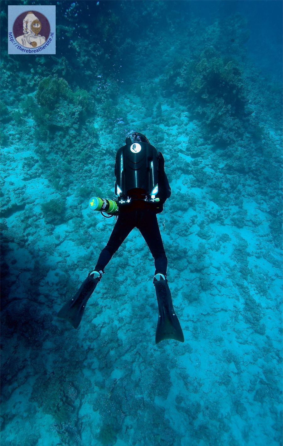
Closed Circuit Research recently introduced the new
Sentinel rebreather.
This webpage describes the design and concept of this new
rebreather. It is a great document for people who are curious why new
rebreathers are introduced to the market. I would like to thank Simon of CCRB
for his kind cooperation to make this article public. A treasure for closed
circuit rebreather divers! But let's start with some nice pictures! Enjoy the
reading.
December 5 2007
please allow some time to load this 2 mb page
Mainmenu:
Search this Website
Information about RB
Photo galleries
Historical Information
Links & Downloads
Reviews
Homebuilders
Electronics
Updates, speed menu
Web shop
Reviews SC rebreathers
Reviews CC rebreathers
RB’s through the ages
Inspiration rebreather
Database Oxygen RB’s
Database Semiclosed RB’s
Updates
Speed menu
Search this web
