Logo Therebreathersite Orifices in rebreathers RSS feed
 
Donate Home Menu page Search page
This pages contains information about very dangerous diving systems. CMF systems are very dangerous in the hands of those who do not understand the system. This information is not a guide to build your own system. It explains some views about diving technology. updated 26 may 2010

Orifices used in semi-closed rebreathers

 Author: Jan Willem Bech

Publication: http://www.therebreathersite.nl

February 2005
 

I wrote this article because many questions were being asked in newsgroups about flow through an orifice. A lot of people are developing manually controlled rebreathers these days. I thought it would be interesting to understand why Dräger used two orifices instead of one for the Dolphin rebreather. In the earlier published article written by Jan Jahns, he explained the physical backgrounds of orifices. This article tries to explain the practical use of the theory. I would also like to shine some light on the results of a wrong IP adjustment of the CMF first stage and what happens if one of the two robins gets clogged in the dosage unit.

Many semi-closed rebreathers are designed to work on the constant mass flow principle (CMF). This kind of rebreather is also called an active semi-closed rebreather. The functioning of the gas supply system in short means the following:

Gas from a cylinder is reduced by a first stage regulator. The intermediate pressure is brought to a very small part in which a restriction hole has been drilled. This component is called an orifice. Gas laws stipulate that in certain conditions the quantity of gas (mass) remains constant. We can therefore inject a fixed mass of gas to the breathing loop of a rebreather.

Since at certain exertion the human body uses the same amount of oxygen at every depth, the quantity of oxygen we have to inject is not depth-related.

The gas mixture composition therefore is not determined by the amount of oxygen we need, but by its partial pressure and by the narcotic effect of inert gasses such as nitrogen. To diminish the narcotic effect of nitrogen and therefore the decompression obligation, we may enlarge the oxygen dosage to a maximum partial pressure of 1.6 bar (military limits 2.0 bar).

If we intend to exceed the depth that is determined by nitrogen sensitivity, helium is to be added (END).

How to choose the right orifice for a certain gas mixture? How to design a gas dosage system of a semi-closed rebreather?

 Let’s start off with a number of basic principles:


  • When dealing with a SC rebreather, a constant dose of Nitrox or Trimix mixture is added to the loop. Only a part of oxygen in the mixture is metabolized.  Consequently, there is a residue of nitrogen mixture escaping from the loop through the overpressure valve.

  • For a closed rebreather, oxygen is added to the loop manually, via a CMF system, or by an electronic manner.

  • In the case of manual control, oxygen partial pressure is read from a display, and if necessary added with a manually controlled oxygen valve (bypass).

  • A CMF system, sometimes also called a KISS system, determines the dosage of oxygen by restriction in a piece of stone or hard metal**.

  • Another much used technique is to make use of a needle (metering) valve.

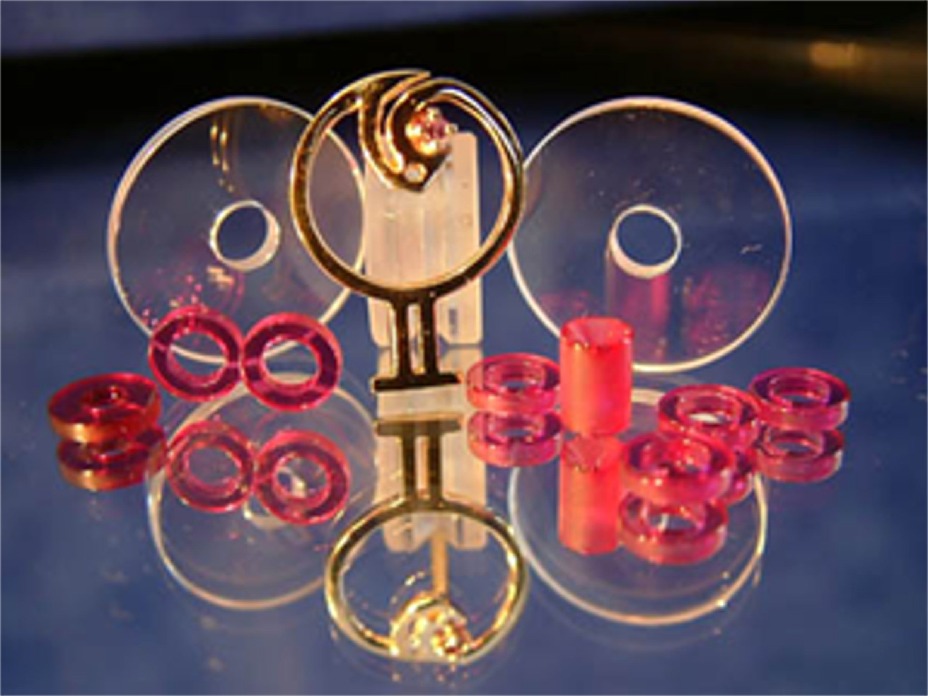
** The orifice is a "synthetic ruby" (actually is "synthetic corundum", Al2O3, the red variety is "ruby", the blue variety is "sapphire"), not a natural gem (it would cost too much to cut a natural gemstone).(Addendum by Gilberto Bonaga, with thanks!)

The use of corundum is due to the fact that it is the harder material after the diamond in the mohs scale and it is possible to produce it industrially at a relative low price.


It is a matter of fine-tuning in such way that the dosage is slightly under the metabolic usage of the diver and only manual correction of the oxygen partial pressure is needed.


In case of an electronically controlled rebreather, oxygen cells measure the oxygen pressure and correct this via an automatic injection system so that the oxygen pressure is close to the ideal oxygen pressure (setpoint) all the time.


In this article I would like to further go into the measurements and choice of orifices and the effect on gas injections during malfunctioning. The link to the active SC rebreathers, as with MCCC rebreathers, can be made because both systems make use of a constant mass flow that is injected into the loop.


The question is to determine how a CMF system works. From Jan Jahns article we learn the following:


  • To achieve a constant mass flow in intended depths, the flow has to be sonic, i.e. with the speed of sound in the critical (narrowest) part of the orifice.

  •  The sonic speed is maintained in depths in which the intermediate pressure is at least twice as high as the ambient pressure.
    (In this example we use Pip/Pamb=2, however there is a more precise calculation)(1)

  •  The amount of gas that is injected into the loop depends on 3 major factors

    • The intermediate pressure

    • The composition of the gas

    • The diameter of the orifice.


Less relevant peripheral factors within this calculation are:

  •   The roughness of the orifice walls

  •   The temperature

  •   The shape of the orifice.


In order to understand the choices of a rebreather design, the following arguments are of interest:

  •  How deep do we want to dive with the SCR system?

  •  What maximum oxygen pressure is acceptable?

  •  What is the maximum oxygen consumption per minute?


CNS and UPTD’s are valid for all rebreathers and are directly related to the used gas. These limits are well known.


Let us answer following queries first.


  1. In case we want to dive to a depth of 40 meters, a minimum IP of 10 bar on our orifices is obligatory.

  2. The nitrogen fraction in the mix is determined by the accepted maximum oxygen pressure and EAD.

  3. The maximum oxygen usage depends on the diver’s activity.

It is important to know the limits of the system. Normally the usage is between 0.3 and 2.5 l/min.

EAD

Taking the Dolphin as a mathematical model.

According to the technical manual of the Dolphin, the intermediate pressure has to be set at 16.7 bar +/- 0.5 bar with the 50/50 dosage nozzle and 100 bar in the cylinder. The orifice will give a flow of  7.3 l/min
For a correct calculation we have to calculate with the absolute pressure, meaning the intermediate pressure + atmospheric pressure = 17.7 bar!


At the same intermediate pressure, the 32% nozzle supplies 15.6 l/min. These data can directly be read from the technical manual. This enables us to calculate the required diameter of the orifice.


Here with the general formula for CMF orifices in a simplified fashion:

Dn= d 2×p0 ×A


Where:

Dn = flow in l/min from the nozzle

d  = orifice diameter in mm

P0  = intermediate pressure in bar

A = gas constant


 For A the following values are applicable

A = 8.65 for pure O2

A =9.233 - 0.00588×O2 [%] for Nitrox

A =9.71 +0.0011×He[%]2  for Trimix (where the result is the most precise in a range of 10-50% helium content)

For example: TMX20/50, d =0.31 mm, p0 = 11 bar :

Dn =A×p0×d2 =13.17 l/min (exacter calculation results in 12.91 l/min)

Coming back to our initial example with the 32% nozzle:

We now know the following

Dn = 15.6 l/min
P0  =17.7 bar

A = 9.233 – (0.00588x32) = 9.04484

Dn=AxP0xd2

15.6 l/min = 9.04484 x 17.7 bar x d2
15.6 l/min = 160.094 x d2
d2 = 15.6 l/min / 160.094
d = 0.31 mm


The orifice that has an opening of 0.31 mm at an IP of 17.7 bar.a  will deliver a flow of 15.6 l/min.
With this configuration the maximum dive depth will be ((17.7:2)-1)10 = 78.5 meter

The fraction of oxygen that is inhaled can be calculated using the following formula:

           (Dn x Fmix) – VO2
FiO2 = --------------------------
                   (Dn-VO2)


Let us first calculate what a diver inhales in the case of a very high metabolic oxygen usage .

In this case VO2 = 2.5 l/min. The gas mixture still is EAN 32

           (15.6 l/min x 0.32 ) – 2.5 l/min
FiO2 = --------------------------------------- = 0.1903
                   (15.6 l/min – 2.5 l/min)

The inhaled oxygen percentage is 19.03%

With normal metabolic usage the diver will inhale VO2 = 1.0 l/min

Then:
           (15.6 l/min x 0.32) – 1.0 l/min
FiO2 = --------------------------------------- = 0.2734
                   (15.6 l/min – 1.0 l/min)

The inhaled oxygen percentage is then 27.34%


Intermezzo:

These values are of course perfect provided that the IP is maintained and that the orifices do not clog up. What would be the consequences when the IP decreases due to incorrect  settings? In case the pressure is set to a lower value of, for instance, 12 bar? Suppose the diver will swim up against the stream and have a VO2 of 2.5 l/min.

The result can be calculated as follows :

Dn=A.P0.d2

Dn = 9.04484 x 12 bar x 0.322
Dn = 11.11 l/min


BTW: at 50 meter the mass flow will decrease because the speed of the gas will drop down into the subsonic region.

Flow

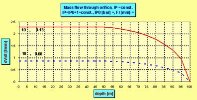
Example with an IP of 11 bar.a. The CMF flow curve drops starting at 45 meter


           (11.11 l/min x 0.32) – 2.5 l/min
FiO2 = -------------------------------------------- = 0.123
                   (11.11 l/min – 2.5 l/min)

The inhaled oxygen percentage is then only 12.3%! The mixture is hypoxic and the diver will 
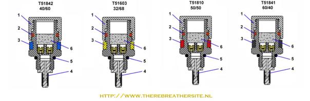
become unconscious.


Another risk is that the orifice gets clogged up. Normally in such cases the flow will stop and no fresh gas will be added to the loop. In case of the Dolphin,  Dräger added extra safety in their dosage device.

The Dräger Dolphin’s dosage device is fitted with TWO orifices per nozzle. The flow is divided over these two orifices. In case one gets clogged up the other one will maintain the gas flow in such way that the diver can safely finish his dive!

injector

Let’s check this with a calculation;

Suppose the diver checked his rebreather and measured the flow. When the IP is carefully adjusted to 17.7 bar.a, the 32% nozzle is connected and the flow test done with 100 bar in the cylinder, there should be a flow of 15.6 l/min.

In case one of the orifice gets clogged up the flow will be cut in half, resulting in a 7.8 l/min. When the diver has a VO2= 1.0 l/min, what will be the oxygen percentage left to breathe?

               (7.8 l/min x 0.32) – 1.0 l/min
FiO2 = -------------------------------------------- = 0.22 %
                   (7.8 l/min – 1 l/min)

In case of normal metabolic oxygen use of the diver no problems will occur. The diver will be able to end his dive breathing 22% of oxygen!

When the diver increases his efforts by swimming faster or against the current, a
VO2 of 1.5 l/min is a more realistic value

                (7.8 l/min x 0.32) – 1.5 l/min
FiO2 = -------------------------------------------- = 0.16 %
                   (7.8 l/min – 1.5 l/min)

There is still 16% in the loop. When the VO2 is further increased there is a risk of hypoxia.

It is clear that by using double orifices extra safety is added to the system. However, when the diver has a high VO2 there is still a big risk. For this reason the measurement of the PO2 is essential!

We can calculate the inner diameter of one of the 32% orifices in this way:

IP=P0=17.7 bar
A = 9.233 – (0.00588x32) = 9.04484
Dn=7.8 l/min

Dn=A.P0.d2

7.8 l/min = 9.04484 x 17.7 bar x d2
d = 0.22 mm per robin.

Dosage units of the Dräger Dolphin:

Tabel1

All right, another example with the 50% dosage unit:

IP=P0=17.7 bar.a
A = 9.233 – (0.00588x50) = 8.939
Dn=7.3 l/min for two robins. For 1 robin = 3.65 l/min

Dn=A.P0.d2

3.65 l/min = 8.939 x 17.7 bar x d2
3.65 l/min = 158,2203 d2
d=
0.15 mm per nozzle

Calculation of the oxygen fraction with VO2=1 l/min and two working orifices

           (7.3 l/min x 0.50) – 1.0 l/min
FiO2 = -------------------------------------------- = 0.42 %
                   (7.3 l/min – 1.0 l/min)


There is 42% of oxygen in the loop.

Calculation of the oxygen fraction with VO2=1 l/min and one working orifice:

           (3.65 l/min x 0.50) – 1.0 l/min
FiO2 = -------------------------------------------- = 0.31 %
                   (3.65 l/min – 1.0 l/min)

There is still 31% of oxygen in the loop!

Note, although we can calculate the flow through orifices now, the flow always has to be tested and measured before the dive. Besides the flow, the partial pressure and MOD should be carefully monitored. When using semi-closed or closed rebreathers, a specialized training program has to be followed! The calculation, as used above, has been the basis for the dosage unit of Jan Jahns. He used restriction orifices used in the gas-heating industry! Check out his rebreather here: ..\SemiClosed Rebreathers\Germany\draeger_sms_1.htm


Thanks to:

 Caroline Kraaijveld
Jan Jahns

The following information is added as a result of the conversation I had with Jahn Jahns and Dave Thompson.

To get more precise calculations the factor  
Pip/Pamb=2 can be calculated more accurate.
When
Poisson constant of oxygen k =cp / cv gives 1.416 and
pcrit / p0  =[2/(
k +1)] k/(k -1)  =B then B = [2/(2,416)] 3,403846 = 0,5256.
The values of the inverted ratio p0 /pcrit =1/B = 1/0,5256 = 1,9026
Calculations should be made with the more precise factor 1,9026

Example:  if the IP gauge reads 10 bar the absolute pressure is 11 bar.
This 11 bar.a / 1,9026 gives a IP of 5,78 bar meaning a depth of 47,8 meters!

After the publication of this article a conversation between Dave Thompson, Jan Jahns and me (Janwillem Bech) followed. Since this article is very interesting I added it with permission to complete this article.


Van: David Thompson [mailto:dave.thomp@virgin.net]

Verzonden: maandag 7 februari 2005 15:05

Aan: jw.bech@quicknet.nl

Onderwerp: cmf


Hi Janwillem


Hope you are well. I have been reading your article on CMF stuff and  I am not so sure it is a sonic flow. First the kiss system of adding o2, it is important that the flow drops as we go deeper otherwise the o2 added would be too great with increasing depth.

For CMF to work it has to be 2 x ambient for upstream IP to make the gas sonic, "maybe" in a  kiss valve the IP is typically set at 7bar (old

orifice) or 10-11 bar (new orifice)


If the CMF rule were to be true then the old orifice would cease to work at 25m and the new one at 40-50m. This of course does not happen (fortunately) because what we DON'T want is a cmf flow! We need the o2 flow to reduce in comparison with depth so the diver continuously receives the correct number of o2 molecules. This slowing of the flow keeps the amount of o2 that's is required by the diver constant in the face of increasing pressure.


Now this is as I understand it and that of course may be wrong :))))


Best


Dave


----- Original Message -----

From: "J.W.Bech" <jw.bech@quicknet.nl>

To: <jahns@quick.cz>

Sent: Monday, February 07, 2005 7:56 PM

Subject: FW: cmf


Jan;


Dave T sent me this answer to the article. The KISS IP Dave mentioned

in my opinion is not correct. The old ones 10 bar IP the new 12 bar IP.

What are your thoughts about his statement?


Janwillem


-----Original Message-----
From: Jan Jahns [mailto:jahns@quick.cz]
Sent: 07 February 2005 21:48
To: jw.bech@quicknet.nl
Cc: dave.thomp@virgin.net
Subject: Re: cmf
 
Hi, JW and Dave,
I´ll try to answer:
 
1. Any gas flow is sonic (i.e. the speed at the critical section equals the local sound speed) when the pressure ratio p0/p1>=cca 2 (in our case p0=IP, p1=ambient press.) "cca" means it depends a little on the gas whether mono- or biatomic etc. So it has to be sonic when p0=7 bar and p1= e.g. 3 bar (20 m). At about 25 m the flow starts to cease with depth (becoming subsonic) and fully ceases when p1=7 bar (60 m). That´s simple.
 
2. In the KISS RB the steady flow cca 0,8 lpm should be adjusted giving hypo-metabolic flow of O2 in depths of use. It is adjusted adjusting the p0 (=IP). The plug in the water inlet of the 1st stage ensures the constant absolute IP in any depth. Reading the KISS manual find in the table of adjustment of flow (for a 0.0035 = cca 0.09 mm diam. orifice): p0=9bar: 0.5 lpm, 10 bar: 0.6 lpm, 11 bar: 0.7 lpm, 12 bar: 0.8 lpm, 13 bar: 0,9 lpm (calculations using the O2 flow formula give 0.61, 0.68, 0.75, 0.82 and 0.89 lpm). In the manual 15% difference is declared as allowable. I haven´t found values for 7 bar but the flow would be insufficient then (about 0.4 lpm).
 
3. Adjustment of IP on 12 bar ensures the flow being sonic up to cca 50 m.
Then the flow slowly decreases (my calculations give 0.82 lpm-sonic-in 50 m, 0.80 in 60 m, 0.75 in 70 m, 0.72 in 80 m, 0.62 in 90 m and then rapid decrease -in 100 m to 0,45 lpm and of course zero in 110 m). That simply
means: going deeper, over the sonic limit, you have to use the manual add valve more often.
 
4. Even the manual states: "The metering orifice flow rate will diminish as the depth (ambient pressure) increases. How much it decreases depends on the upstream pressure (regulator pressure setting) versus the downstream pressure (depth). This is not a fault, it is physics." (end of citate).  The decrease of the flow when crossing certain critical depth is not intentional, it is simply the matter of  p0/p1 < cca 2.
 
5. Regarding the "correct number of O2 molecules": remember that the flow
(0.8 lpm) is the normal pressure volume pro minute in any correct depth (not ambient pressure related volume) so the number of molecules in the dose is always the same in any depth (statistically, of course:-).
 
I hope my answer is satisfying enough, if not, let me know why, guys.
Wishing clear water around. Jan.
 
Well, during writing this sentences I obtained your next e-mails. But I think everything is explained in this answer. I’ve got my figures from the new manual (for 0.08 mm orifice) as you can see. Regarding diving deeper then to "sonic limit" see the upper calculations for 80 meters: the flow makes always 0.72 lpm which doesn’t differ much from 0.82 lpm in 50 meters.
Compare also with the plot of CMF in the article on mass flow.. The drop starts at critical depth but is not very rapid except at the depths where the ambient press. draws near to the IP. Greetings.
 
Jan Jahns
 
-----Oorspronkelijk bericht-----
Van: David Thompson [mailto:dave.thomp@virgin.net]
Verzonden: maandag 7 februari 2005 23:39
Aan: 'Jan Jahns'; jw.bech@quicknet.nl
Onderwerp: RE: cmf
 
Ok I think I understand most of that but one thing bothers me if I understand your reasoning correctly  and you were to plot the flow on a graph, you would have a pretty straight line until the flow went subsonic then it would curve off?
 
If that is correct that is not what seems to happen in practise
 
I notice no additional need to touch the add button when deep over when shallow.  An example, I need to set my IP to give a flow of 0.68lpm (this matches my metabolic rate when diving) with this set and at 65m I did one hour on the bottom (the deck of a huge ship in nice clear water) and I didn’t touch the manual add button once. The IP set to give this flow is 10bar (according to my gauge) if your theory/ maths is correct it should have gone sub-sonic at 40m, is this correct?
 
Thank you for your help and explanations
 
Dave
 

-----Original Message-----
From: J.W.Bech [mailto:jw.bech@quicknet.nl]
Sent: 07 February 2005 23:35
To: 'David Thompson'
Cc: jahns@quick.cz
Subject: RE: cmf
 
Dave; Jan;
 
Greetings. Very interesting! Dave, when I look at the curve it doesn't curve off. It seems almost flat until 80 meter.
I think what Jan supposed would be similar to your findings Your VO2=0,68 and 70 m= 0.72 in 80 m= 0.62.(how many injections would be needed for the 0,68 & 0,62 difference?) In my opinion that would explain your findings.
 
 
This message reached me too:
 
"the orifice is a "sinthetic ruby" (actually is "sinthetic corundum", Al 2O3, the red variety is "ruby", the blue variety is "sapphire"), not a natural gem (it would cost too much to cut a natural gemstone).
 
The use of corundum is due to the fact that it is the harder material after the diamond in the Mohs scale and it is possible to produce it industrially at a relative low price.
"
The person telling this is Gilberto Bonaga a geologist.
 
OK for now, good night;
 
 
Janwillem
 
I do wonder however if its not sonic but just simple physics "double the pressure, halve the volume" type of stuff, we are just lucky that it fits perfectly with our metabolic needs!!!
 
A couple of engineers I spoke to (who know far more about this than I ever
will) also doubt the sonic  flow of this type of gas addition
 
They argue that were it sonic you would see a large change in the gas addition once the 2 x ambient upstream pressure diminished!!!
 
Anyway very interesting conversation guys
 
Best
 
Dave


-----Original Message-----
From: Jan Jahns [mailto:jahns@quick.cz]
Sent: 08 February 2005 21:27
To: David Thompson; jw.bech@quicknet.nl
Subject: Re: cmf
 
Well, then
 
I´ve made some recalculations of the flow depending on depth according to your  low O2 consumption rate. I suppose you used normal pressure gauge and your reading was 10 atm gauge, i.e. 11 ata (absolute) (1). My calculations give about 0.61 lpm (for 0.08 mm orifice) then, but  let´s take your actually measured value 0.68 lpm as the base for following calculations.
More exactly the calculated critical ratio p0/p1 = IP/(ambient pressure) is not 2 but 1.9026(2) and 11/1.9026 gives 5.78 bar of the ambient pressure, i.e.
47.8 meters as the maximum depth in which the flow changes from sonic to subsonic. At this depth the flow rate is always 0.68 lpm and only then started to diminish. The calculated flow rates are then: in 50 m the 3 th decadic place does not change giving always 0.68 lpm. At 55 m I obtained
0.676 lpm. In 60 m: 0.663 lpm and in 65 m: 0.645 lpm. Seems the little difference (0.035 lpm) is not serious for your needs, Dave :-).
To calculate the subsonic flow is a little bit more complicated then the sonic one but is not very difficult and your engineering friends sure could do it as well. (3) I use spreadsheet calculator to do the math but during the long period of use I´ve built in much balast so it´s readable for me only now.
Regarding your doubts about the sonic speed and precise mass flow in the sonic region:
The gas expands adiabatically into place of lower pressure, cools down and the speed of sound at this temperature is the critical one which cannot be overcome -in the critical section of the orifice (usage of  properly formed – so called “Laval – nozzle” can enhance the speed downstream of the nozzle up to Mach 2). This speed is maintained then even if the downstream pressure grows - (e.g. in confined space) but only up to this given by the mentioned ratio (calculations in the article). Only then it becomes subsonic.
The mass flowing out equals then (see Continuity Equ.:) (cross-section) x
(speed) x (critical density). As all 3 variables are constant in the sonic region also the mass flow is maintained constant.
 
Greetings, Jan.
 
Excellent, thanks for your help, that makes it more understandable to my
non- engineer mind :))
 
Best
 
Dave


13 Februari 2005
Oosthuizen Netherlands
11:17
 
 
Jan:
 
Reading all this I still have three questions:

(Jan Jahns answers follow directly in colour Red)

 
So for the calculations we use the ABSOLUTE pressure and not the measured pressure on the IP gauge! I.e when a IP is measured of 16,7 bar as Dräger stated in the technical manual the calculations should be made with a absolute IP of 17,7 bar? (I changed the values in the article). http://www.therebreathersite.nl/01_Informative/orifices_in_rebreathers.htm  Or do they give the gasflow for a measured IP?
 
I think Dräger IP values are in bar-gauge for custom convenience, so 1 bar has to be added to obtain the absolute pressure, really. There is only 1 place in Draeger manual concerning the IP which I have found to be 240 psi/16.5 bar (not psig/ata!). During the check of your article I hold not in mind these parameters and I supposed you used absolute pressure. In my article I always mentioned it as well as in graphs.
But really again: Dräger allowed flow tolerances are 11% and the flow using either values (16.7 bar vs. 17.7 bar) lies in 6 % tolerance (the flow is proportional to IP). The calculated orifice diam. using 17.7 bar changes from 0.156 to 0.162 mm. It makes only a little difference, nevertheless it is methodically wrong if 16,7 is used in the calculations.
 
 
You stated that in this case the p0/p1 = IP/(ambient pressure) is not 2 but 1.9026. The values of the inverted ratio p0 /pcrit =1/B lie for the breathing gases in the range 1,90 -2,05, i.e. p0 /pcrit   in average aproximately equals 2.
What factor(s) determin this exact calculation? In other words, how did you calculate the 1.9026 factor in Dave’s case?
It´s simple: I took κ = 1.416 for O2 (which I use in my calculation spreadsheet) and inserting it to the formula you can find 6 rows down I got B = 0,5256 which inverted gives 1/B = 1.9025875, rounded 1.9026.
 
Should the flow velocity be sonic (equal the velocity of sound) we have to put w2 =c2 and from equations derived we obtain that for the ratio p/p0  (i.e. for the ratio of the outlet to inlet pressures) following condition has to be fulfilled:
                   pcrit / p0  =[2/(k +1] k/(k -1)  =B .  
Here pcrit  is the critical pressure in the critical section of the nozzle and from the formula follows that if the outlet pressure p is  lower or equal to pcrit , i.e. if  p/p0 £ B holds in the critical section the local sonic velocity wcrit  is achieved which can't be exceeded increasing the inlet pressure p0.
 
 
Could you sent me an example of the subsonic flow calculation, using the calculated examples you sent to Dave and me.
 
The calculated flow rates are then: in 50 m the 3 th decadic place does not change giving always 0.68 lpm. At 55 m I obtained
0.676 lpm. In 60 m: 0.663 lpm and in 65 m: 0.645 lpm. Seems the little difference (0.035 lpm)
 
As I wrote it´s a problem: I wrote the programs for myself so there are many odds which currently only I understand. I have to rewrite some but it takes time. Nevertheless: (I prefer using bigger Arial to make types in formulae beter readable). Using asterix for multiplication sign.
 
D = dVn / dt  (normal liters pro minute) = 1/ρn * dM / dt = 1/ρn * S * w * ρ,
M - mass (kg), ρ – density (kg/m3)  in orifice, ρn – normal density = 1.409 kg/m3  for O2 , S = π * (d/4)2 –cross section of the orifice and w – the velocity of gas in the orif. – now subsonic ! It could be calculated by the help of formula you can find some rows lower.  Insert IP (absolute) as p0 , ρ0 = ρn * (p0/pn ), ρ = ρ0 * (p/p0)1/κ .  Put all variables in the above bold formula , do some algebra and you have the right formula into which the correct figures can be inserted.
Notice: There are mostly ratios of pressures there, so mostly bars could be used, only once in the √  you have to use 101300 (Pascals ) for pn . Inserting  d in mm you also have to divide the result by 10002  (=106), then multiplicate by 1000 (mm = 1 m) and by 60 (seconds in 1 minute).
 
Jan thanks for the efforts!
 
Janwillem Bech
 
You are welcome, JW


Jan Jahns
 
 Inserting e.g. the value of k for biatomic gases gives the value B=0,528.
 The values of the inverted ratio p0 /pcrit =1/B lie for the breathing gases in the range 1,90 -2,05, i.e. p0 /pcrit   in average aproximately equals 2. It means again that the inlet pressure p0  being at least the double of p -the outlet one -the velocity in the nozzle is sonic. But being lower, e.g. p0  =1.5 p the velocity would be subsonic.
 The above reasoning implies following: holding the inlet pressure p0  constant (independent of depth) and equal 10 bars (absolute)  the velocity (i.e.also the gas flow as we´ll see later) is sonic up to depth in which the ambient pressure is half of it, i.e. up to 40 meters, in which the ambient pressure is 5 bars. The velocity in the nozzle of air whose inlet temperature has been 0°C is in each depth up to 5 bars  303 m/s. But going deeper the velocity decreases onto 230 m/s in 60 m
(according w =Ö{ [2.k/(k -1)].p0/r0 .[1 -(p/p0) (k -1)/k]} ), onto 105 m/s in 80 m and the flow would stop in 90 m (where ph =10 bar ºp0).


Jan Jahns and Dave Thompson, thanks for the value added to this article!

         
Webshop Guestbook mail: jw.bech@quicknet.nl