|
Principles of Constant Mass Flow or How does the Dräger Dolphin Work? Nevil Adkins
|
|||||||||||||||||||||
|
Note: the following information is mainly theoretical in nature, has not been checked by others, is not issued by Dräger and may not be 100% correct. As an engineer I have applied my knowledge of thermodynamics and hopefully this will give an insight as to how the Dolphin works. Introduction The Dräger Dolphin and its stable mate the Ray are recreational Semi-closed Circuit Rebreathers (SCRs) using a constant mass-flow design to add gas to the breathing loop. They are very similar in nature so I will talk of the Dolphin and highlight where the Ray is different where I can (I use the Dolphin, not the Ray so may not know all the differences). The basic nature of the beast is taught on the relevant user course and will not be dwelt on here. For further reference read the user manuals supplied with the units and “Rebreather Diving”[1] by Bob Cole. Many questions have been raised on various e-mail groups about how the Dolphin will react when changing the interstage pressure, diving deep, using different gas mixes, etc. The explanations that have ensued have been vague, confusing or even wrong in some circumstances so I will attempt to explain the engineering theory that drives the Dolphin. The theory is quite simple in principle but to really get to terms with it you need some heavy-duty maths. For those who want the inside story refer to “Engineering Thermodynamics”[2] by Rogers and Mayhew. The relevant chapter is Chapter 18 – One Dimensional Steady Flow and Jet Propulsion.
Background theory |
|||||||||||||||||||||
|
|
|||||||||||||||||||||
|
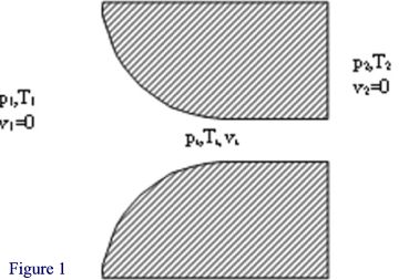
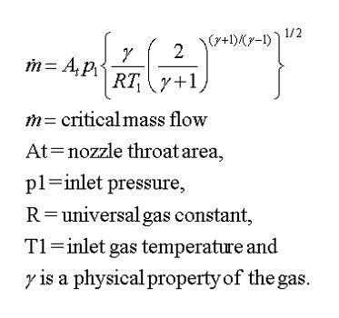
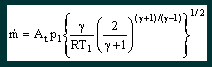
Gas in a large container has an initial pressure p1, temperature T1 and velocity v1 which is negligible. The ambient pressure at the outlet of the nozzle is p2. Since p2 is lower than p1, the gas feels a pressure difference resulting in an accelerating force. The gas begins to move towards and through the nozzle. The gas’s potential energy in the form of pressure is gradually converted to kinetic energy in the form of velocity. As the inlet pressure is increased, the gas feels a greater acceleration force and the velocity achieved in the throat of the nozzle increases. At a certain point however the difference in pressure between p1 and p2 is sufficient to accelerate the gas to the speed of sound at local conditions in the throat of the nozzle (pt, Tt), a barrier that cannot be passed. A further small increase in the initial pressure p1 (potential energy) cannot increase the velocity (kinetic energy) in the throat so the gas still has some potential energy left – the throat pressure pt rises above the ambient pressure p2. As the gas exits the nozzle it becomes unconstrained and expands irreversibly to the ambient pressure p2, decelerating instantly to low velocity. If at this stage the ambient pressure were to be lowered then the gas conditions in the nozzle do not change and no extra flow occurs. Similarly if the ambient pressure is raised, as long as it does not rise to match the throat pressure again, no influence on the throat conditions are felt and the flow rate remains constant. This situation is known as choked flow and achieves constant mass flow for given inlet conditions, regardless of how the outlet conditions vary. What happens if the inlet pressure is increased further? Since only a fraction of the initial potential (pressure) energy is needed to accelerate the gas to the speed of sound (kinetic energy), more potential energy is left over and the pressure in the throat rises. This increases both the local speed of sound and the gas density, which results in a greater mass flow. Thus, once choked flow is achieved, variations in outlet (ambient) pressure will have no effect on the mass flow rate, but variations in inlet pressure will cause corresponding variations in the mass flow rate. The rigorous mathematical analysis in Engineering Thermodynamics leads to the equation |
|||||||||||||||||||||
|
|
|||||||||||||||||||||
|
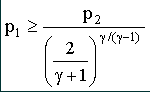
From this equation it can be seen that the critical mass flow for a particular nozzle (i.e. fixed At) is a function of the inlet pressure and temperature and the nature of the gas passing through it. Critical mass flow is achieved provided that |
|||||||||||||||||||||
|
|
|||||||||||||||||||||
|
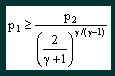
where p2 is the nozzle outlet pressure.
From this equation it can be seen that the critical
pressure ratio (p2/p1) is a function solely of the
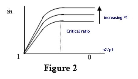
nature of the gas passing through the nozzle. What happens if the critical pressure ratio is exceeded? Provided that the pressure ratio p2/p1 is less than the critical value then the nozzle will be choked and a constant mass flow regime will be achieved. What happens if the critical ratio is exceeded? The answer is that the velocity in the throat of the nozzle will not reach local sonic and the nozzle will not be choked. The flow rate will gradually reduce until no flow occurs when the pressure ratio is unity, i.e. there is no pressure difference. The characteristic is illustrated in the graph, figure 2. |
|||||||||||||||||||||
|
|
|||||||||||||||||||||
|
What is γ? The physical property of the gas known as γ, is the ratio of the specific heat capacities at constant pressure and volume and can be measured for each gas. The γ for a mixture of gases such as nitrox can be calculated if the composition of the gas is known and the γ for each component is known. For example: |
|||||||||||||||||||||
|
Table 1
|
|||||||||||||||||||||
|
How does this theory relate to the Dolphin? The gas contained in the cylinder of the Dolphin is reduced to a fixed interstage pressure by the first stage regulator. The output of this first stage is held constant at 250psi/17.2bar gauge, irrespective of depth. This contrasts to the usual open circuit and Ray regulator design, which maintains the interstage pressure at a fixed margin (typically 10bar/140psi) above the ambient pressure. The gas is then taken to the dosage jets which each contain two laser drilled rubies that act as nozzles according to the above theory. The holes in the rubies are sized to give a certain flow rate with a certain gas mix, within a certain tolerance band. From the basic theory outlined above let us take Equation 1 |
|||||||||||||||||||||
|
|
|||||||||||||||||||||
|
and deduce the consequences. 1. T1 is the absolute inlet temperature to the jets, measured in Kelvin. Due to expansion through the regulator it is likely to be a few degrees cooler than ambient, but probably not significantly. For the most part we dive in water temperatures between say 273 K (0°C) and 303 K (30°C), a variation of ±5% from the average 288 K (15°C). This variation will only change the mass flow by ±2.5% so can probably be ignored totally, and certainly over the duration of a single dive. 2. The mass flow is related in a complex way to the properties of the mix flowing through the nozzle. Whilst considering nitrox, the variation in γ between EAN32 and EAN60 is about 0.2%, which leads to a variation in the mass flow of about 0.08%. Even dramatically changing nitrox mixes will not affect the mass flow rate flowing through any particular jet. 3. The mass flow is directly proportional to the inlet (interstage) pressure, p1. Any variation in the interstage pressure, whether by intent or mishap, will directly affect the mass flow rate. For example, dropping the interstage pressure from 18.2 bar absolute to 13.6 bar absolute will reduce the mass flow rate of each of the jets by 25%. Now let us take Equation 2 |
|||||||||||||||||||||
|
|
|||||||||||||||||||||
|
and deduce the consequences. 1. If the interstage pressure p1 is fixed at 18.2 bar absolute, then the mass flow will remain constant provided the ambient pressure p2 is less than a certain value, dependant on γ. For nitrox mixes p2/p1 must be less than 0.526. This implies that the maximum ambient pressure for critical mass flow is 9.6bar absolute, or approximately 86m. This is way in excess of the 40m limit for recreational use or 52m limit for military use recommended by Dräger. 2. If the interstage pressure p1 is allowed to vary, either by accident or design, the maximum depth achievable whilst retaining critical flow will also vary. How does this theory relate to the Ray? Unlike the Dolphin, the first stage of the Ray reduces the pressure in the cylinder to an interstage pressure at a fixed margin above ambient pressure – this is the same as most open circuit regulators. The gas is then taken to the dosage jet, there is only one, which like the Dolphin contains two laser drilled rubies that act as nozzles according to the above theory. The Ray is specified for diving to a maximum of 22m with EAN50. From the basic theory outlined above let us take Equation 1 |
|||||||||||||||||||||
|
|
|||||||||||||||||||||
|
and deduce the consequences. 1. As for the Dolphin, the variation in flow rate with temperature is miniscule and can effectively be ignored. 2. As with the Dolphin, the mass flow is related in a complex way to the properties of the mix flowing through the nozzle. Since the Ray is specified for use only with a single mix there should be no variation in γ but as we have seen for the Dolphin the variations in γ, and the subsequent variations in the flow rates are also negligible with varying nitrox mixes. The Ray could therefore be used with a number of different mixes, albeit with the limitation of choice of flow rates. 3. The mass flow is still directly proportional to the inlet (interstage) pressure, p1, but unlike the Dolphin this is not fixed. The jet inlet pressure at is related to the depth in the following manner: |
|||||||||||||||||||||
|
|
|||||||||||||||||||||
|
|
|||||||||||||||||||||
|
which for a typical interstage pressure of 10bar becomes |
|||||||||||||||||||||
|
|
|||||||||||||||||||||
|
Referenced to the flow rate at the surface, the flow rate at the specified maximum depth of 22m will be 20% higher. The gas consumption of the Ray is therefore not independent of depth as the Dolphin is but the reduction in unit duration from 1½ hours at the surface to 1¼ hours at 20m is insignificant for the majority of recreational users at whom this unit is aimed. Now let us take Equation 2 |
|||||||||||||||||||||
|
|
|||||||||||||||||||||
|
which for nitrox reduces to |
|||||||||||||||||||||
|
|
|||||||||||||||||||||
|
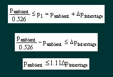
Solving Equations 3 & 5 gives |
|||||||||||||||||||||
|
|
|||||||||||||||||||||
|
which for our typical interstage pressure of 10 bar means Pambient ≤ 11.1bar or 101m |
|||||||||||||||||||||
|
The Ray will not stray out of the critical ratio limitation until extreme depth – but don’t forget the mass flow is not constant across the depth range! The Ray is still not suitable for diving much beyond the recommended maximum of 22m. Does the Dolphin/Ray use “supersonic” flow? No. The gas passing through the nozzle accelerates from negligible velocity until it achieves sonic velocity at local conditions of temperature and pressure. Theoretically the gas could be further accelerated as it leaves the nozzle, to achieve supersonic velocities, but this would not increase the mass flow. Furthermore the nozzle would have to be very carefully (and expensively) engineered, and very minor variations in conditions would quickly bring the nozzle off its design point. The gasses leaving the nozzle expand instantaneously and irreversibly, and decelerate back to negligible velocity. Supersonic velocities are not needed. How will using trimix affect the Dolphin? Modern thinking is that diving beyond 40m should be done using trimix. The section on the Dolphin above shows that the maximum theoretical depth for the Dolphin should be in the range of 80m. How will using trimix in the Dolphin in the 40-80m range affect performance? Returning to equation 2 reminds us that the critical pressure ratio is dependant on γ, which is itself a function of gas composition. Extending table 1 to include helium and trimix gives |
|||||||||||||||||||||
|
|||||||||||||||||||||
|
table 2 |
|||||||||||||||||||||
|
It can be seen that even very high helium mixes such as TMX10/80 only have a γ about 12% higher than EAN32. The increase in γ reduces the critical pressure ratio slightly, making the maximum ambient pressure for critical mass flow 9.1bar absolute, or approximately 81m – not greatly different from the 86m theoretical limit calculated for nitrox. The difference is that 81m is a feasible dive on trimix but not for nitrox! The increase in γ will also be reflected by an increase in mass flow rate of about 4% for any particular jet. This is well within the tolerance band of individual dosage jets and below the measurement accuracy of most people and will not realistically affect dive planning. This theory is confirmed by several people’s experience in using the unit on trimix. The conclusions from these calculations match up interestingly with the reports that Dräger have developed a modification pack to allow the Dolphin to be used to 80m on trimix. How would feeding the dosage jets from a standard regulator affect the Dolphin? It has been suggested to feed gas to the dosage jets from a second source via a standard regulator. In this way it would be possible to feed a rich nitrox or pure oxygen to the loop during decompression. As noted in the section regarding the Ray, the use of depth compensating regulators will result in variable flow rates. Since decompression using rich mixes is usually only carried out over a small range of depths, the variation would not be that great and could be coped with. If however the gas fed to the jets was a bottom gas, say from a side-slung cylinder acting as either a bail-out or as a main cylinder, then the system would be very dynamic in nature. If set up to give correct flow rates at the surface, large quantities of gas would be wasted at depth. If set up to give correct flow rates at depth then the oxygen mass flow rate at shallow depths might not be sufficient to meet demands with dire consequences. As per the Ray, use of depth-compensating regulators to feed gasses to the dosage jets should not be considered deeper than about 22m. I hope this look at the physics driving the Dolphin and Ray has been readable, and more importantly correct. If anybody wishes to offer corrections, suggestions for further areas of coverage, etc. then please contact me at adkinsoman@yahoo.com |
|||||||||||||||||||||
|
[1] Rebreather Diving, Bob Cole, published by Sub-Aqua Association 1998, ISBN 0 9519337 9 5. [2] Engineering Thermodynamics – Work & Heat Transfer 4th Edition, Rogers & Mayhew, published by Longman Scientific & Technical, ISBN 0-582-04566-6. |
|||||||||||||||||||||